


Chapter 4: Configuration
724-746-5500 | blackbox.com
Page 29
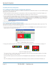
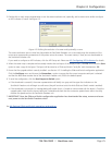
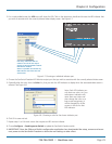
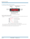
Figure 4-7. Choosing an individual indicator port
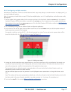
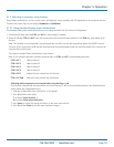
4. Choose the ServSwitch Freedom LED Monitor output port that you wish to associate with the currently selected video screen.
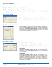
5. Optionally alter the color, from the Color: list, that you wish the LED indicator to display when the associated video screen is
selected. See Figure 4-8.
3. For a newly added screen the LED: entry will show No LED. Click on the drop down handle and choose the LED indicator that
you wish to associate with the currently selected video display screen. See Figure 4-7.
Each entry within the LED: list
relates to one of the ten output
sockets on the ServSwitch Freedom
LED Monitor module.
Note: It is possible to associate any
LED indicator with more than one
video screen.
Figure 4-8. Choosing a color for the chosen indicator port
6. Click OK to save and exit.
7. Repeat steps 1 to 6 for each screen that requires an LED monitor indicator.
8. Choose Configure > Send Layout to Switch to update the ServSwitch Freedom switch.
9. IMPORTANT: Once the Glide and Switch configuration application has downloaded the setup, remove and recon-
nect power to the ServSwitch Freedom to allow the new settings to take effect.
Note: Each LED indicator can
only have one color, so if you
associate an indicator with
more than one screen and
then change the color on a
later screen assignment, it
will be changed for all the
screens in the list for that
LED indicator.