


Chapter 2: Overview
724-746-5500 | blackbox.com
Page 9
COMPUTER K/M SPK USB1 USB2 MODE
ServSwitch Freedom
™
BLACK
BOXDESKTOP
KVM
SWITCH
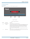
2.5 Hardware Description
2.5.1 Top Panel
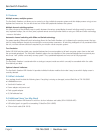
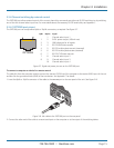
Figure 2-2 shows the top panel of the unit. Table 2-1 describes its components:
Figure 2-2. Top panel.
Table 2-1. Top panel components.
Number Component Description
1 COMPUTER button Press to change to the next computer channel.
2 Indicators The lower four indicators (K/M, SPK, USB1, USB2) show which peripherals are switched
to the current computer channel or (as you begin pressing the MODE button) the
peripherals that will be switched during the next press(es) of the COMPUTER button.
The upper four indicators scroll across at regular intervals whenever the Glide and
Switch channel switching system is enabled.
The seven-segment numeric display indicates the computer channel that is currently
active.
3 MODE button Press to determine which peripherals should be switched to another computer channel
(will occur when you press the COMPUTER button).
1
2 3