


Black Box Modular Switches
Installation and User Guide (8/99)
16
3.0
Installation
Before installing the equipment, it is necessary to take the
following precautions:
1.) If the equipment is mounted in an enclosed or multiple rack
assembly, the environmental temperature around the equipment
must be less than or equal to 50
0
C.
2.) If the equipment is mounted in an enclosed or multiple rack
assembly, adequate air flow must be maintained for proper and
safe operation.
3.) If the equipment is mounted in an enclosed or multiple rack
system placement of the equipment must not overload or load
unevenly the rack system.
4.) If the equipment is mounted in an enclosed or multiple rack
assembly, verify the equipment’s power requirements to prevent
overloading of the building/s electrical circuits.
5.) If the equipment is mounted in an enclosed or multiple rack
assembly verify that the equipment has a reliable and
uncompromised earthing path.
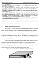
Installation:
This section describes installation of the LE14XXA-Series Switches, as well as
connection of the various Ethernet media types.
3.1
Locating LE14XXA-Series Switches
The location of a LE14XXA-Series Switch is dependent on the physical layout of the
network. Typically the Switch is placed in a central wiring location where groups of network
devices need to be connected in
order to communicate with each other. These Switches are
typically rack mounted in a wiring closet see Section 3.3.2 below), but because they have rubber
feet they can also be installed on a shelf or table top. The compact size of the 8
-port LE1401A
unit a
llows it to be easily placed in an office or lab area, and it can also be either shelf of wall-
mounted (see Section 3.3.1 below).
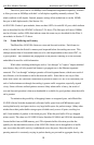
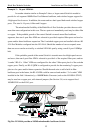
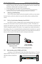
Locate an AC receptacle that is within six feet (2 meters) of the intended LE14XXA-
Series site. The rugged metal case of t
he LE14XXA-Series will normally protect it from
accidental damage in a lab or workplace setting. Maintain an open view of the front to visually
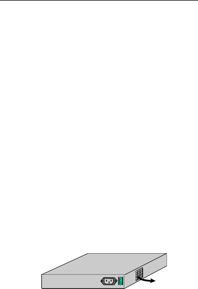
monitor the status LEDs. Keep an open area around the unit so that cooling can occur from the
small fan on the
left side, while the unit is in operation. See figure below.
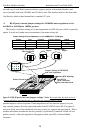
Figure 3.1: Location of 8-port LE1401A’s cooling fan exhaust
ON
OFF
110-220
VAC
47-63Hz
1.0-0.5A
FAN EXHAUST