


Black Box Modular Switches Installation and User Guide (8/99)
27
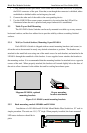
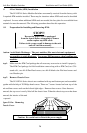
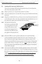
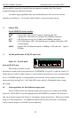
Looking down into the LE14XXA-Series unit, notice that there are individual 4PM
connector sockets along with two stand-offs for each 4PM card position. There are four 4PM
sl
ots located on the front of the LE1416Amodel, whereas LE1401A and LE1408A has two 4PM
slots in the front. (See Figure 3.9.1b).
Figure 3.9.1b: LE1416A, Top View with Chassis Cover
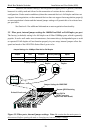
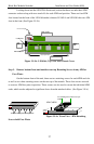
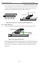
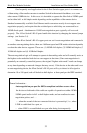
Step 3. Remove bottom-front and modules rear top Retaining Screws in any 4PM or
Face Plates
On the bottom-
front of the unit, there are two retaining screws for each 4PM card slot
as well as two other retaining screws on the rear top of the module. These four screws are used
to secure a 4PM face plate in position. These scr
ews are also used to secure the individual 4PM
cards, which can be subjected to significant forces from the attached cables. (See Figure 3.9.1c)
Figure 3.9.1c: Front View - 4PM Retaining
Screws hold Face Plates
Front of Unit
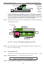
Media Connector
with electronic
elements
Right
Side
Left
Side
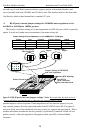
Cooling Fan
Power Supply Board
LED Status Slot
Eight QPM Slots
AC Power Input
Back of Unit
GARRETT
Magnum QS5116
Fiber Switch
Two Bottom retaining Screws for each QPM card
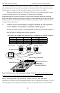
1
4PM CARDS
GARRETT
Magnum QS5116
Fiber Switch
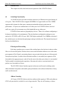
J1 J2 J3
J4Printed Circuit card
TOP
Two retaining screws on the rear top of
module