Black Box Modular Switches Installation and User Guide (8/99)
29
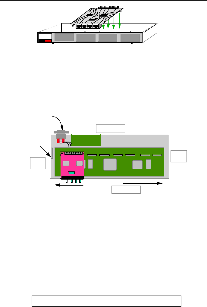
Figure 3.9.2a:
Inserting
4PM Cards
into a
LE1416A
NOTE: All 4PM slots need not be filled in order for the LE14XXA-
Series unit to be
operational. When leaving 4PM slots empty, always use a face plate ( 4PM-FP) to
cover the slot opening in the front panel. This will maintain proper cooling air flow,
safety, and operation as required by FCC, CE, and other regulations.
Step 7. The figure below shows the top view of 4PM Card after successfully installed the
4PM
cards inside the LE1416A.
Fig. 3.9.2b Top View : 4PM Module Installed inside a LE1416A
Step 8. Once all 4PM cards have been installed (including face plates for empty slots), the
chassis cover should be replaced.
3.9.3 Removing 4PM Cards
To properly remove a 4PM card from the Fiber Switch, follow the 3 steps below.
Step 1. Remove chassis cover See procedure in Section 3.9.1 above.
Caution: Be sure the power cord is unplugged.
Step 2. Remove bottom-front retaining screws for the 4PM and Face Plate
1
4PM CARDS
J1 J2 J3
J4Printed Circuit card
TOP
GARRETT
Magnum QS5116
Fiber Switch
Front of Unit
Media Connector
with electronic
elements
Right
Side
Left
Side
Cooling Fan
Power Supply Board
Four QPM Slots
AC Power Input
Back of Unit


