


Black Box Modular Switches
Installation and User Guide (8/99)
26
3.9
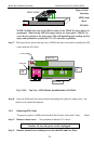
4 Port Module (4PM) Installation
The LE14XXA-Series Modular Switches are normally received from the factory with
all required 4PM modules installed. There may be situations where 4PM cards need to be added
or replaced. In cases where additional 4PM cards are needed, the face plate for an available front
-
mounted slot must be removed. The fo
llowing procedure describes this operation.
3.9.1
Preparation for Installing and Removing 4PMs
STOP!!!
Be sure the power cord is unplugged
from the chassis before attempting to remove
and/or replace any 4PM cards.
Failure to do so may result in damage to the unit
and will void the warranty.
Caution
- Avoid Static Discharge: The port modules (like most electronic equipment)
are sensitive to static discharge. Use proper ESD measures when handling port
modules.
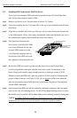
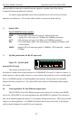
Step 1.
Make sure the 4PM Card package has all necessary accessories to install it properly.
The 4PM Card package for field installation comes along with a 4PM Card, two 7/16
stand-offs , two #4-40 Pan-Head screws, two #4-40 black color Flat-head screws and
two Headers pin.
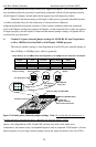
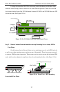
Step 2.
Remove Chassis Cover
The LE14XXA-Series chassis are combined with top and bottom part and assembled
together with the help of 20 Philips head screws. There are 7 screws located on front
-top of the
unit
and three screws each on the left and right edges. Remove these screws. Once these are
removed, the top cover is easily lifted off the chassis base. When the chassis top cover has been
removed, the interior of the unit
is exposed.
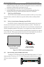
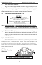
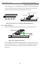
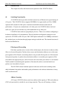
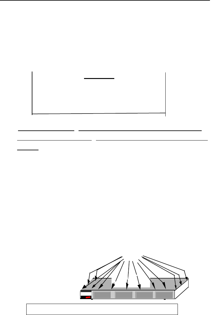
Figure 3.9.1a:
Removing
Chassis Cover
Caution: Be careful not to disturb the power supply.
Power Input
20 Phillips Head Screws on Top
PWR
GARRETT
TopChassis Cover
Magnum QS5116
Fiber Switch