


Black Box Modular Switches
Installation and User Guide (8/99)
30
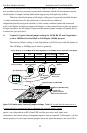
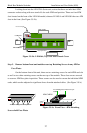
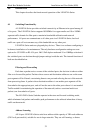
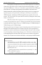
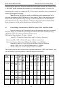
On the bottom-front of the unit there
are two retaining screws for each 4PM card and face plate slot. These screws are used
to secure a 4PM card in position (see Figure 3.9.3a). Remove the front screws first
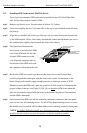
and then screw mounted on the rear-top of the 4PM to be removed.
Figure 3.9.3a: Front View - Face Plate & 4PM Retaining Screws
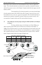
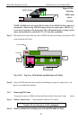
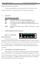
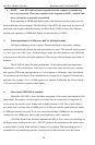
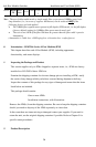
Step 3.
Remove 4PM Card
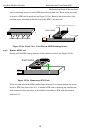
Gently pull the 4PM card up and out of the connector socket (see Figure 3.9.3b).
Figure 3.9.3b: Removing a 4PM Card
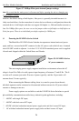
If the slot from which the 4PM card has been removed is to remain unused, be sure to
install a 4PM face plate cover in it. If another 4PM card is replacing the one that has
been removed, follow the steps as described for installing a 4PM card discussed in
Section 3.9.1.
GARRETT
Magnum QS5116
Fiber Switch
Two Bottom retaining Screws for each QPM card
1
4PM CARDS
GARRETT
Magnum QS5116
Fiber Switch
J1 J2 J3
J4
Printed Circuit card
TOP
Two retaining screws on the rear top of
module
1
4PM CARDS
J1 J2 J3
J4
Printed Circuit card
TOP
GARRETT
Magnum QS5116
Fiber Switch