


ASYNC ROUTER AR-P, AR-5, AND SYNC ROUTER USER’S MANUAL
72
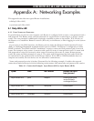
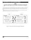
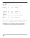
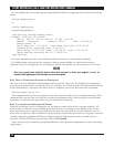
The routing table entries are:
• Sync Router A
Destination /Bits Interface Router/Next Hop Metric
128.66.0.0 /16 eth0 0
128.66.14.0 /24 eth0 128.66.1.2 2
default /0 sync0 10.4.0.106 1
• Sync Router B
Destination /Bits Interface Router/Next Hop Metric
128.66.14.0 /24 sync0 128.66.14.1 1
128.66.14.0 /24 modem0 128.66.14.1 3 redundant
128.66.0.0 /16 eth0 0
default /0 eth0 128.66.1.1 1
• Sync Router C
Destination /Bits Interface Router/Next Hop Metric
128.66.14.0 /24 eth0 0
default /0 sync0 128.66.1.2 1
default /0 modem0 128.66.1.2 3 redundant
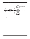
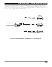
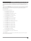
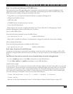
Router B has redundant routes to the 128.66.14.0 subnetwork. Similarly, Router C has redundant
default routes. As long as the synchronous link is operational, Router B will use it to reach subnetwork
128.66.14.0, because the route through the sync0 interface has a lower hop count (metric=l) than the
route through modem0 (metric=3):
Similarly, Router C uses the synchronous link to reach any other location, because the route through
the sync0 interface has a lower hop count (metric=l) than the route through modem0 (metric=3).
If the synchronous link fails, Router B and Router C maintain connections by automatically
transferring traffic to their integrated modems.