


724-746-5500 | blackbox.com
724-746-5500 | blackbox.com
Page 11
NBS008A
Chapter 2: Overview
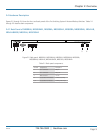
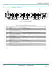
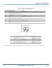
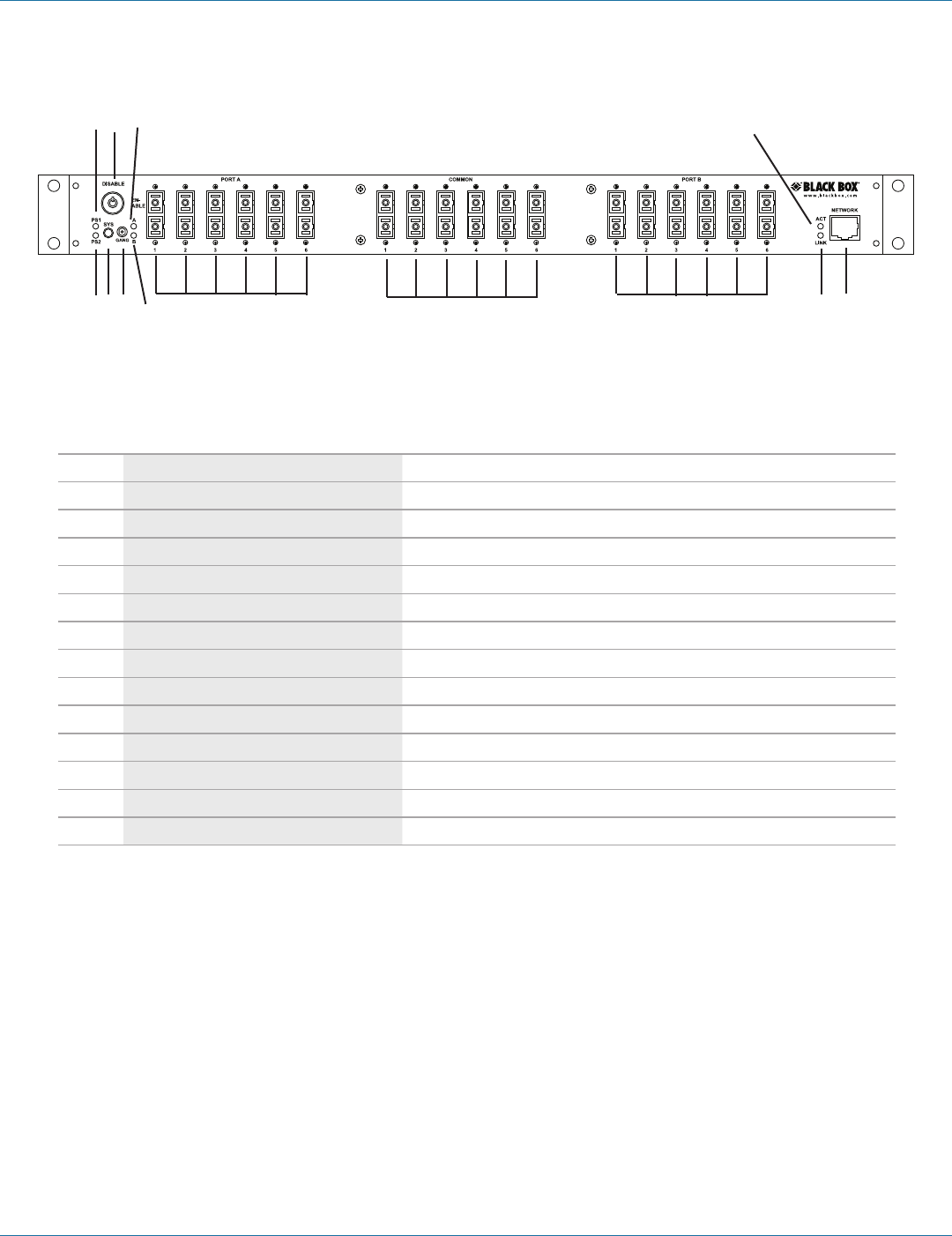
2.4.3 Front Panel of NBS006A, NBS006MA
7 8 9 10 11 12 13 14 15
16 17 18 19
Figure 2-4. NBS006A, NBS006MA.
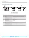
Table 2-3. NBS006A, NBS006MA front panel components.
Number Component Description
7 PS2 LED Lights when power supply 2 is on.
8 Sys switch Momentary pushbutton switch selects an entire system of daisychained switches.
9 Gang switch Used for manual switching.
10 “B” LED Lights when ports connected to Port B are linked to the Common Ports.
11 (6) duplex SC connectors Link to Port A.
12 (6) duplex SC connectors Connect to Common Ports.
13 (6) duplex SC connectors Attach to Port B.
14 Link LED Lights when switch is connected to the network.
15 RJ-45 connector 10/100 network port.
16 PS1 LED Lights when power supply 1 is on.
17 Manual disable switch (key lock) Must be in the position labeled ENABLE for manual switching to occur.
18 “A” LED Lights when ports connected to Port A are linked to the Common Ports.
19 Act LED Lights when there is network activity.