


724-746-5500 | blackbox.com
Page 12
NBS008A
724-746-5500 | blackbox.com
Chapter 2: Overview
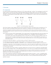
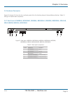
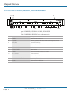
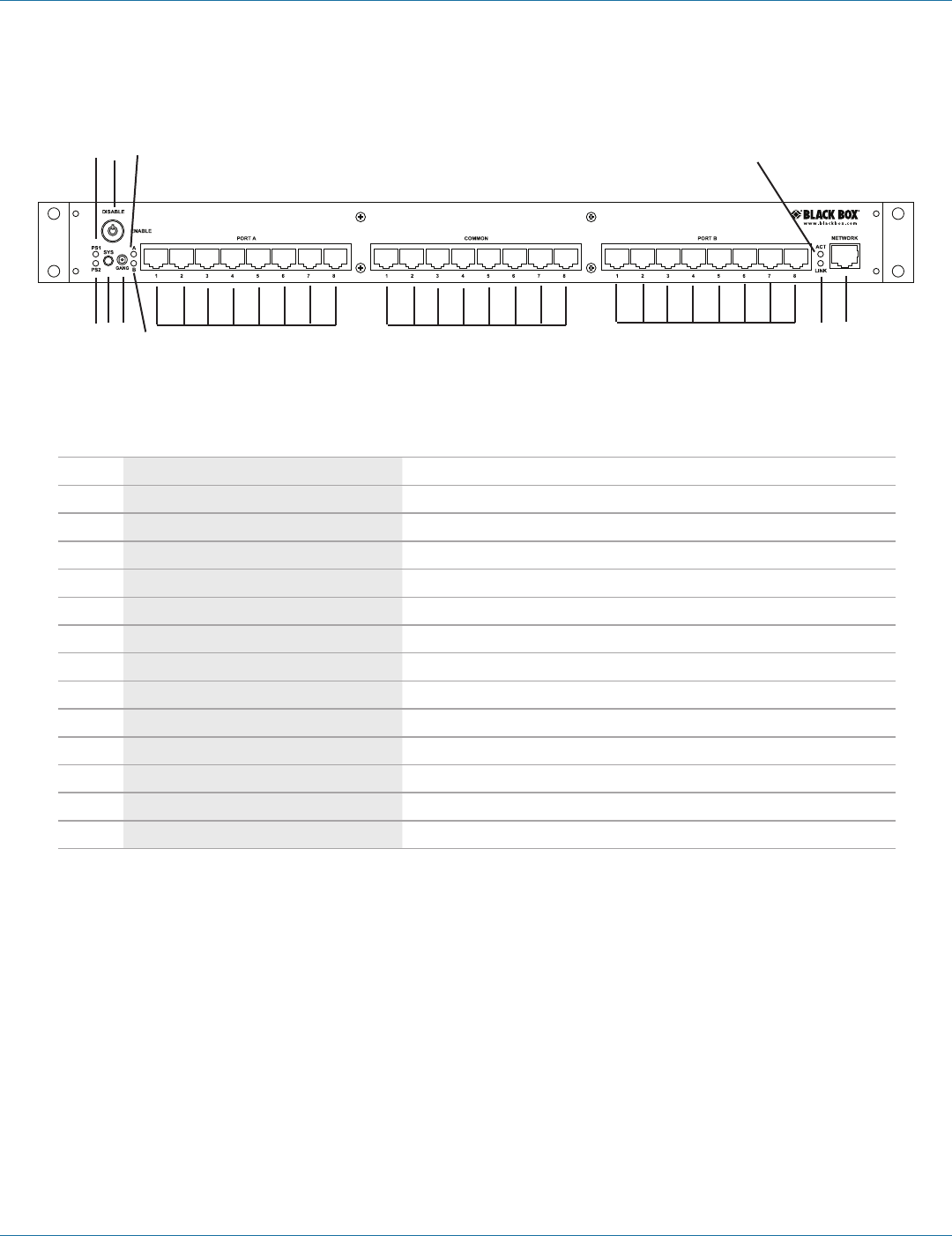
2.4.4 Front Panel of NBS008A, NBS008MA, NBSALL8, NBSALL8MGR
7 8 9 10 11 12 13 14 15
16 17 18 19
Figure 2-5. NBS008A, NBS008MA, NBSALL8, NBSALL8MGR.
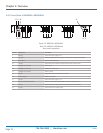
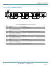
Table 2-4. NBS006A, NBS006MA front panel components.
Number Component Description
7 PS2 LED Lights when power supply 2 is on.
8 Sys switch Momentary pushbutton switch selects an entire system of daisychained switches.
9 Gang switch Used for manual switching.
10 “B” LED Lights when ports connected to Port B are linked to the Common Ports.
11 (8) RJ-45 connectors Link to Port A.
12 (8) RJ-45 connectors Connect to Common Ports.
13 (8) RJ-45 connectors Attach to Port B.
14 Link LED Lights when the switch is connected to the network.
15 RJ-45 connector 10/100 network port.
16 PS1 LED Lights when power supply 1 is on.
17 Manual disable switch (key lock) Must be in the position labeled ENABLE for manual switching to occur.
18 “A” LED Lights when ports connected to Port A are linked to the Common Ports.
19 Act LED Lights when there is monitor activity.