


724-746-5500 | blackbox.com
724-746-5500 | blackbox.com
Page 9
NBS008A
Chapter 2: Overview
2.4 Hardware Description
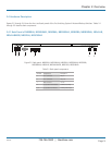
Figures 2-2 through 2-6 show the front and back panels of the Pro Switching System 4 Network Backup Switches. Tables 2-1
through 2-5 describe their components.
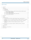
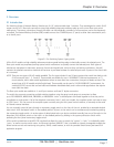
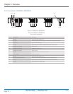
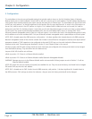
2.4.1 Back Panel of NBS004A, NBS004MA, NBS006A, NBS006MA, NBS008A, NBS008MA, NBSALL8,
NBSALL8MGR, NBS016A, NBS016MA
1 2 3 4 5 6
Figure 2-2. Back panel: NBS004A, NBS004MA, NBS006A, NBS006MA, NBS008A,
NBS008MA, NBSALL8, NBSALL8MGR, NBS016A, NBS016MA.
Table 2-1. Back panel components.
Number Component Description
1 RJ-11 connector Gang in
2 RJ-11 connector Gang out
3 DB9 connector Console
4 (2) 8-position DIP switches (1) Addr, (1) Config
5, 6 (2) 4-position connectors 12-VDC power input