


18
MATRIX SERVSWITCH™
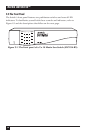
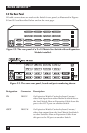
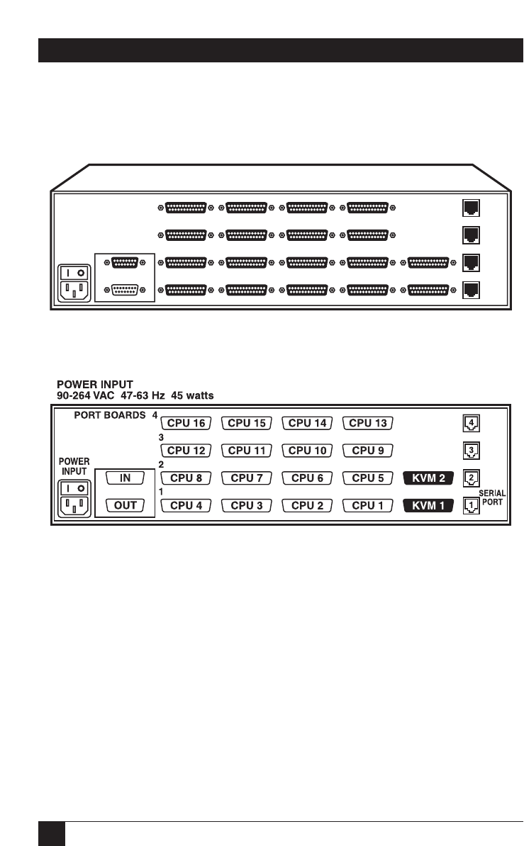
2.4 The Rear Panel
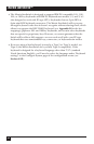
All cable connections are made at the Switch’s rear panel, as illustrated in Figures
2-2 and 2-3 and described below and on the next page.
Figure 2-2. The rear panel of a 2 x 16 Matrix ServSwitch with an Expansion
Module installed.
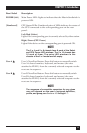
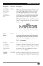
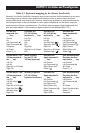
Figure 2-3. The same rear panel, board and port numbering shown.
Designation Connector Description
On Expansion Module: Carries keyboard/mouse/
video data output from the local Matrix ServSwitch
to other Switches. Run an Expansion Cable from
this port to the IN port on another Switch.
DB15 M
OUT
On Expansion Module: Carries keyboard/mouse/
video data input from other Matrix ServSwitches
to
the local Switch. Run an Expansion Cable from this
port to the OUT port on another Switch.
DB15 F
IN