


29
CHAPTER 3: Installation and Preconfiguration
3.3 Installation Procedure
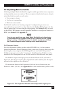
This section provides complete instructions for the hardware setup of a single
Matrix ServSwitch. (For detailed instructions on installing a daisychained Matrix
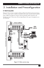
ServSwitch system, see Sections 3.3.6 and 3.4.) For an illustrated example of the
elements of a basic setup, see Figure 3-1.
For the procedure you should use to power up the system, see Section 3.5. For
the initial configuration procedure, see Section 3.6.
IMPORTANT NOTE
Initially configuring a Matrix ServSwitch will require you to either attach
a monitor, keyboard, and mouse to one of its KVM ports or to attach a
complete computer system to one of its serial ports. If this attachment
will be difficult to make after a particular Switch has been physically
installed in a given location, you should configure that Switch before
you install it; see Section 3.6.
3.3.1 PLACEMENT
The Matrix ServSwitch is best located as close as possible to the CPUs that are
attached to it. This reduces the length of CPU cables and provides a more cost-
effective, neater installation. You should also place the Switch as close as possible to
the AC outlet you want to plug it into.
CAUTION!
Avoid routing cable near fluorescent lights, air-conditioning
compressors, or machines that may create electrical noise. Total length
of original Serv type CPU or User Cable (not including Expansion Cable)
from the keyboard, monitor, and mouse to any given CPU should not
exceed 40 ft. (12.2 m). For typical equipment and
video resolutions,
length of coaxial
CPU or User
Cable (again, not including Expansion
Cable) should not exceed 20 ft. (6.1 m)
from a Matrix ServSwitch to any
attached device (keyboard, monitor, mouse, CPU, or other KVM switch).
However, we do provide coaxial cable in lengths up to 100 ft. (30.5 m),
because some CPUs can drive and receive keyboard and mouse signals
at greater distances than others. To go even farther, you might want to
use Station Extenders or CAT5 KVM Extenders (see Appendix B).
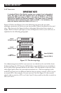
3.3.2 SETTING AND INSTALLING THE OPTIONAL EXPANSION MODULE
At any time, you can swap in an Expansion Module for the Terminator Module in
the Matrix ServSwitch’s Expansion slot, in order to prepare the Switch to be
daisychained. Depending on the topology of your daisychained system, you might
need to set the Expansion Module’s JP1 jumper before you do this. For directions,
see Appendix E.