


21
CHAPTER 3: Installation and Preconfiguration
3. Installation and Preconfiguration
3.1 Quick Setup Guide
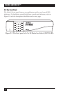
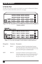
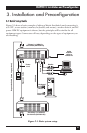
Figure 3-1 shows a basic example of taking a Matrix ServSwitch and connecting it
to a CPU, a user station (monitor, keyboard, and mouse), another Switch, and AC
power. IBM PC equipment is shown, but the principles will be similar for all
equipment types. Connectors will vary depending on the types of equipment you
are installing.
Figure 3-1. Basic system setup.
Power
cord
CPU Cable
User Cable
Expansion Cable (forms ring, optional)
Expansion Cable
Primary 2 x 16 Matrix
ServSwitch (SW743A-R3)
Secondary 2 x 16 Matrix
ServSwitch (SW743A-R3)
Mouse
Video card
Keyboard
Mouse
Keyboard
Monitor
6-wire
modular
cable to
remote PC