


19
CHAPTER 2: Introduction
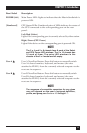
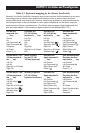
Designation Connector Description
NOTE
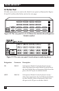
The 2 x 4 and 2 x 8 chassis have 8 each
of the CPU-port slots. The 2 x 16 chassis
has 16 of them. The extra slots in the
chassis of the 2 x 4 model are left blank,
but are protected by material mounted
inside the chassis.
Connect the Matrix ServSwitch’s power-supply cord
here. The Switch’s internal transformer is autosensing
and can handle either 110-VAC or 230-VAC input.
IEC 320 M
[POWER
INPUT]
If you connect a more distant computer or
terminal to this RS-232 serial port, you’ll be able to
send switching commands to the Matrix ServSwitch
from a secondary location. You would also connect
a computer to this port to upgrade the Switch’s
firmware. Refer to Chapter 7.
RJ-12 F
RS-232 N
[N = a number
from 1 to 1, 2, or
4, depending on
which model you
have]
Connect the shared monitors, keyboards, and mice
to this port using User Cables. At the Switch end,
these cables have a DB25 male connector; at the
other ends, they have appropriate connectors to
plug into your monitor, keyboard, and mouse
cables. See Section 2.5.
DB25 FKVM 1 and
KVM 2
Connect the sharing computers to these ports with
CPU Cables. At the Matrix ServSwitch end, these
cables have a DB25 male connector; at the other
ends, they have appropriate connectors to plug
into your CPUs’ video, keyboard, and mouse ports.
These cables take the signals that would normally
pass between the CPUs’ ports and the monitor,
keyboard, and mouse, and carry them between the
CPUs’ ports and the Switch instead. You must have
one CPU Cable for each CPU you plan to connect.
See Section 2.5.
DB25 F
N [CPU N]
[N = a number
from 1 to either
4, 8, or 16,
depending on
which model you
have]