


IV-22
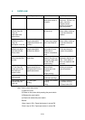
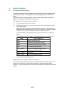
5. TROUBLESHOOTING MALFUNCTIONS
When carrying out countermeasures for malfunctions as described in this section, check
connectors for contact failure before measuring the voltage at the specified connector
pins.
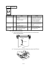
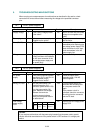
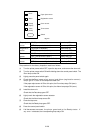
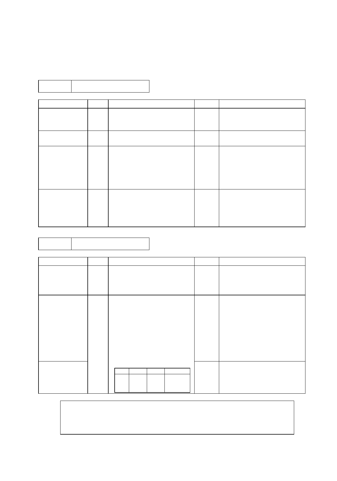
M-1 No AC power supplied
Possible cause Step Check Result Remedy
Supply voltage 1 Is the correct voltage present
at the outlet?
No Inform the user that the correct
voltage is not supplied at the
outlet.
Power plug 2 Is the power cord securely
plugged into the outlet?
No Plug the power cord securely
into the outlet.
Fuse (F1, F2) 3 Is the fuse blown? Yes If the fuse blows again
immediately after replacing the
low-voltage power supply PCB,
check that there is not a short
circuit somewhere in the AC
power supply line.
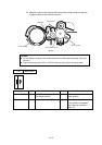
Wiring 4 Unplug the power supply plug.
Is there a broken wire between
the AC input connector of the
low-voltage power supply and
the power plug?
Yes Replace the AC power cord.
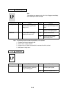
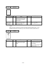
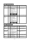
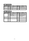
M-2 No DC power supplied
Possible cause Step Check Result Remedy
AC power
supply
1 Is AC power supplied between
connectors CN1-L and CN1-N
when the power plug is
plugged into the outlet?
No Follow the same check
procedure of M-1 “No AC
power supplied”.
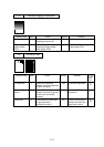
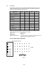
Wiring, DC load 2 Turn the power switch OFF
and disconnect the P13
connector (panel sensor PCB).
Turn the power switch ON
again. Measure the voltages
between the terminals.
Do the measured voltage
satisfy the prescribed value in
the table below?
Yes Turn the power switch OFF,
reconnect the connector and
turn the power switch ON
again.
If the protector circuit is
activated, check the connector,
the wiring from the connector,
and the DC load.
Low-voltage
power supply
PCB
PCB + lead pin - lead pin Voltage
Panel
Sensor
P8-1 P8-4 Approx. 24V
P8-2 P8-3 Approx. 5V
No Replace the low-voltage power
supply PCB.
Caution:
If you analyze malfunctions with the power plug inserted into the power outlet, special
caution should be exercised even if the power switch is OFF because it is a single pole
switch.