Features
6C105 Overview and Setup Guide 1-5
1.7 FEATURES
Redundant Power Supply Modules
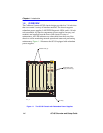
The 6C105 supports two power supply modules which reside in the slots
labeled PS1 and PS2.
Each power supply module supports an ac input connector that allows
each power supply to be connected to a separate ac power source.
Cabletron Systems also offers a power supply module that supports a DC
input connector that allows each power supply to be connected to a
separate DC power source. In addition, the power supply modules are
capable of load sharing 50% (+/- 5%) of the total load presented by the
6C105. If one of the power supply modules fails, the other power supply
module supplies the entire load of the chassis without interruption to
network traffic.
Power Supply LANVIEW LEDs
Each power supply module comes equipped with LEDs for at-a-glance
diagnostics that indicate individual power supply status and overall
chassis redundancy status. Refer to Chapter 2,
Installation
Requirements and Specifications
, for a full explanation of the power
supply LEDs and their definitions.
Power Supply Status Via Local Management
The 6C105 power supply modules report information to the modules
installed in the chassis regarding the present operating status. This
information includes the following:
•
Power Supply ID (PS1, PS2)
•
Power Supply Status (normal/fault/not installed)
•
Power Supply Redundancy Indication (redundant/not available)
•
Fan Tray Status (normal/fault/not installed)
Refer to the module specific User’s Guide for instructions on how to
access power supply status information via Local Management.
!
CAUTION
If the 6C105 is configured with a single power supply module it
must
be located in slot PS1.
Installing one ac power supply and one DC power supply in the
same chassis is NOT allowed.


