


FDDI Management
4-10 Alarm Configuration
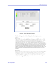
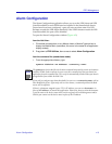
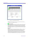
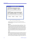
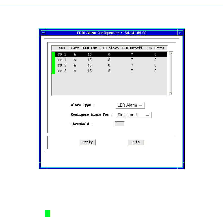
Figure 4-5. Alarm Configuration Window
The Port List Box in the upper portion of the window displays the following
information for each FDDI port in the hub:
(Port Alarm Status)
The color displayed in this box indicates the LER Alarm status of each listed port:
green indicates that the port’s LER Estimate is below the LER Alarm threshold;
yellow indicates that the port’s LER Estimate has equaled or exceeded the LER
Alarm threshold, and the port is in an alarm state; and red indicates that the port’s
LER Estimate has equaled or exceeded the LER Cutoff threshold, and the port has
been disabled.
SMT Index
Displays the index number of the Station Management (SMT) entity to which
each port is attached. Each FDDI NIM module has two SMT entities — one for
each front panel interface. If you have launched the Alarm Configuration
application from the Hub View Module menu, these two SMT entities will be
indexed by front panel interface numbers (FP 1 and FP 2, as illustrated above); if
you have launched the application from the command line (or if your 7C0x hub
has more than one FDDI NIM installed), the front panel designations will not