


3-10
Switch Hardware
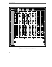
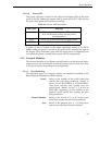
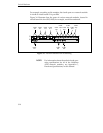
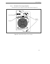
For example, according to this notation, the fourth port on a network module
in slot B of switch board #2 is port 2B4.
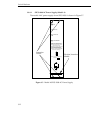
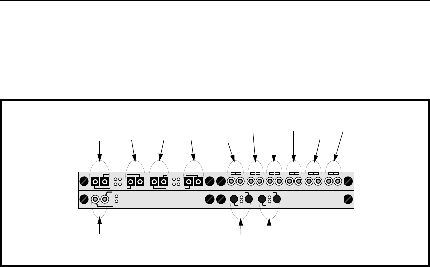
Figure 3.6 illustrates how the ports of various network modules, located in
switch board #4 of an SFCS-1000, for example, would be numbered.
Figure 3.6 - Network Module Port Numbering
NOTE: For information about the technical and oper-
ating specifications for all of the Cabletron
ATM network modules, see Appendix C,
Hardware Specifications, in this manual.
C
AB
D
RX1
TX1
RX2
TX2
RX3
TX3
RX4
TX4
TX2
RX2
TX1
RX1
PORT PORT
4B1 4B2
PORT PORT PORT PORT
4C1 4C2 4C3 4C4
TX1
RX1
PORT
4A1
R1 R2 R3 R4 R5 R6T1 T2 T3 T4 T5 T6
PORT
PORT
PORT
4D1
4D2
4D3
PORT
PORT
PORT
4D4
4D5
4D6