


Fiber Optic TPIM Specifications
Page A-4
A.3.2 TPIM-F3 for Single Mode Fiber
The TPIM-F3 connector supports Single Mode Fiber Optic cabling.
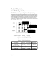
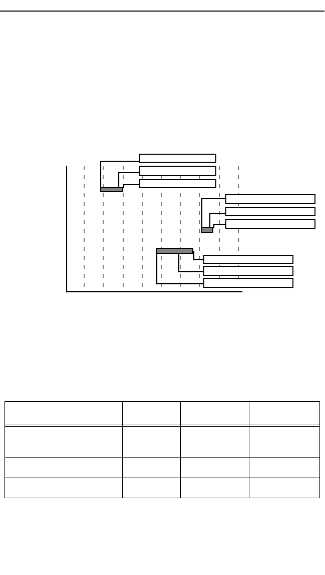
Transmitter Power decreases as temperatures rise. Use the Output Power
Coefficient (-0.15 dBm) to calculate increased or decreased power output
for the operating environment. For example, the typical power output at
25°C is -16.4 dBm. For a 4°C temperature increase, multiply the typical
coefficient (-0.15 dBm) by four and add the result to typical output power:
(4 x -0.15 dBm + -16.4 = -17.0).
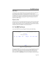
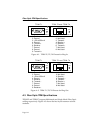
Figure A-4. Transmitter Power Levels
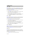
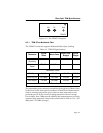
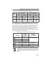
Table A-3. TPIM-F3 Specifications
Parameter Typical Minimum Maximum
Transmitter
Peak Wave Length
1300 nm 1270 nm 1330 nm
Spectral Width 60 nm – 100 nm
Rise Time 3.0 nsec 2.7 nsec 5.0 nsec
Receive
Sensitivity
dBm
Less Power
More Power
-40 -35 -30 -25 -20 -15 -10 -5 0
Maximum
Receive
Input Power
Transmitter Power*
(At 25°C into
8.3/125µm fiber)
Minimum Sensitivity (-30.0)
Typical Sensitivity (-31.0)
Maximum Sensitivity (-36.0)
Maximum Receive Input (-6.99)
Typical Receive Input (-7.5)
Minimum Receive Input (-9.72)
Maximum Transmit Power (-12.0)
Typical Transmit Power (-15.5)
Minimum Transmit Power (-21.0)
* Transmit Power Typical Power Minimum Power Maximum Power
Coefficient
(See Note Below)-0.15dBm/ °C -0.12 dBm/ °C-0.18 dBm/ °
C