


RF400 Table of Contents
ii
C. RF400 Series Address and Address Mask ...........C-1
D. Advanced Setup Standby Modes ......................... D-1
E. RF400 Series Port Pin Descriptions ..................... E-1
F. Datalogger RS-232 Port to RF400 Series Radio ... F-1
G. Short-Haul Modems ...............................................G-1
H. Distance vs. Antenna Gain, Terrain, and
Other Factors .....................................................H-1
I. Phone to RF400 Series ............................................. I-1
J. Monitor CSAT3 via RF400 Series............................J-1
K. Pass/Fail Tests ....................................................... K-1
L. RF400/RF415 Average Current Drain
Calculations ....................................................... L-1
Figures
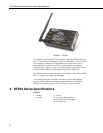
1. RF400......................................................................................................... 2
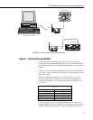
2. RF400 Basic Point-to-Point Network......................................................... 5
3. Point-to-Point LoggerNet Network Map.................................................... 6
4. Some 900 MHz FCC Approved Antennas..........................................16-18
5. Example COAX RPSMA-L Cable for Yagi or Omni Colinear................ 19
6. Antenna Surge Protector .......................................................................... 19
7. Enclosure with Antenna Surge Protector for RF400................................ 20
8. Point-to-Multipoint System...................................................................... 26
9. PC208W Datalogger Generic Dial String ................................................ 27
G-1. Short-Haul Modem to RF400 Setup................................................... G-1
I-1. LoggerNet Point-to-Multipoint Setup....................................................I-4
K-1. Loop-back Test without Antennas...................................................... K-3
K-2. Vertically Polarized 9 dBd 900 MHz Yagi........................................ K-5
K-3. 3 dBd 900 MHz Collinear Omni Antenna.......................................... K-6
Tables
1. Lacking 12 V on CS I/O Pin 8 ................................................................... 5
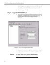
2. Standard Setup Menu................................................................................. 8
3. 15966’s Voltage Regulation..................................................................... 14
4. RF400 Series 12 V Power Supply Options .............................................. 14
D-1. Advanced Setup Menu....................................................................... D-1
H-1. 900 MHz Distance vs. Path Loss (Lp in dB) per Three Path Types ..H-6
H-2. Path Type vs. Path Characteristics Selector....................................... H-6