


Appendix J. Monitor CSAT3 via RF400 Series
J-2
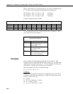
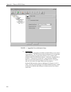
(5) Select “1” for “Standard Setup” and configure the following
(a) Active Interface – leave at default “Auto Sense”
(b) Network Address – can be default “0” if no neighboring RF400
networks are operating; otherwise choose a different network
address (see RX LED Test below).
(c) Radio Address – can be default “0”
(d) Hopping Sequence – can be default “0” if no neighboring RF400
networks are operating; otherwise choose a different hopping
sequence (1 – 6).
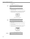
- RX LED Test -
To determine if there is a neighboring RF400 network in
operation using the same hopping sequence as yours, stop
communications on your network and observe RF400 green
LEDs for activity. At this point, any green LED activity would
indicate that there is a nearby network using the same hopping
sequence.
The other network’s network and/or radio addresses might be
different than yours, so having the same hopping sequence isn’t
necessarily a serious problem but having an exclusive hopping
sequence results in fewer retries.
(e) Standby Mode – leave at default “2”
(f) Retry Level – if RF noise is a problem, try “Low” or a higher
level to see if response improves.
(6) Repeat steps 1 - 5 with “remote” RF400. Temporarily use 6 ft. cable
and AC adapter during the remote RF400 setup. CSAT3 monitoring
requires a Point-to-Point network so you should configure all remote
RF400 settings the same as you did for the base RF400.
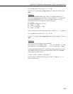
CSAT3 SETUP
(1) Power CSAT3 off and then back on
(2) Connect CSAT3’s RS-232 cable to the desired PC COM port
(3) Run CSAT32 software
(4) Select correct COM port if necessary under Settings\Communication
(5) Enter Terminal mode (bottom tab)
(6) Open Port (if not already open)
(7) Press [Enter] a couple of times to get “>“ prompt
(8) Enter “br 0” and press [Enter] to send it to CSAT3 to configure RS-
232 communications to 9600 baud (the RF400 always communicates
at 9600 baud).
(9) Enter “ri 1” and press [Enter] to send it to CSAT3 to turn on RS-232
drivers (if you want to save this setting in non-volatile RAM, refer to
CSAT3 Instruction Manual, Appendix B).
(10) Return to Data mode (bottom tab)
HARDWARE SETUP
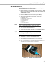
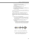
(1) Base station
(a) Plug AC adapter into 120 VAC outlet and barrel connector into
“DC Pwr” jack on base RF400.
(b) Connect 6 ft. cable (from base kit) between PC COM port of
choice and RF400 RS-232 port.