


K-1
Appendix K. RF400/RF410 Pass/Fail
Tests
This appendix describes a method to functionally test RF400/RF410 system
components including:
• PC COM port
• SC12 serial cable
• RF400/RF410
• RF400/RF410 Antenna
Hardware/Software Required
9 PC with one available COM port
9 Terminal Program (HyperTerminal
TM
or Procomm
TM
)
9 Two RF400/RF410s
9 Two SC12 serial cables
9 ¼ wave OMNI antenna (CSI Item # 14310)
9 Two power supplies rated 12 Volts, 1 Amp
(recommend AC adapter Item # 15966 and any 12 V battery pack with
Field Power Cable Item # 14291)
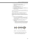
The following descriptions tell how to build an RF400/RF410 loop-back test
system. Recommendations are given as to where to place the system to avoid
rf-reflections (see TESTING ¼ Wave Antenna footnote
2
in this appendix).
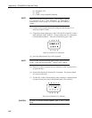
The basic parts of the system are:
1) PC running a terminal program and a serial cable from PC COM port to
base RF400/RF410
2) Base RF400/RF410
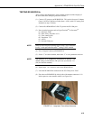
3) Remote RF400/RF410 with RS-232 port jumper wire between TX (pin 2)
and RX (pin 3) for data loop-back.
Build the RF400/RF410 test system in the order shown:
1) TESTING SC12 CABLE and PC COM PORT
2) TESTING RF400/RF410s
3) TESTING ANTENNAS
Label components of the system “known-good” as they pass the test.
TESTING SC12 CABLE and PC COM PORT
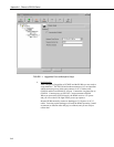
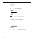
(1) Run a terminal program such as HyperTerminal
TM
or Procomm
TM
(a) Baud rate: 9600
(b) Data, Parity, Stop Bits: 8-N-1
(c) Flow control: none