


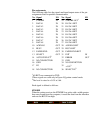
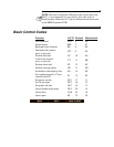

Pin assignments
The following table lists the signals and input/output status of the pin
assignments used for parallel communication.
1
All-RETs are connected to GND.
2
These signals are valid only in Epson LQ printer control mode.
3
The level is raised to +5.0V at 5.6k.
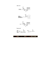
Each signal is defined as follows:
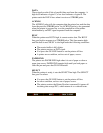
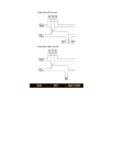
STROBE
When the printer receives the STROBE low pulse with a width greater
than one second from the computer, it reads the data from the interface
and sets the BUSY line high.
No. Signal I/O No. Signal I/O
1 STROBE IN 19
STROBE-OUT
1
2 DATA 1 IN 20 DATA 1-RET
3 DATA 2 IN 21 DATA 2-RET
4 DATA 3 IN 22 DATA 3-RET
5 DATA 4 IN 23 DATA 4-RET
6 DATA 5 IN 24 DATA 5-RET
7 DATA 6 IN 25 DATA 6-RET
8 DATA 7 IN 26 DATA 7-RET
9 DATA 8 IN 27 DATA 8-RET
10 ACKNLG OUT 28 ACKNLG-RET
11 BUSY OUT 29 BUSY-RET
12 PAPER END OUT 30 PAPER END-RET
13 SELECT OUT 31 INIT IN
14
AUTO FEED XT
2
32 ERROR OUT
15 NO CONNECTION 33 GND
16 GND 34 NO CONNECTION
17 FG 35
+5.0V
3
18 NO CONNECTION 36
SELECT IN
2