


1-11
Cisco Content Delivery Engine 100/200/300/400 Hardware Installation Guide
OL-13478-03
Chapter 1 Overview of the Content Delivery Engines
Hardware Features
Input/Output Ports and Connectors
The CDEs support the following I/O connectors on the rear of the device:
• Ethernet connector
• Serial connector
• Video and audio connectors (on optional adapter)
Caution Once the product installation is complete, all I/O cables, except those installed in the Ethernet ports,
must be disconnected from the CDE to maintain EMC compliance. Any other cable connections are
temporary and are only used to initialize the system. All PS/2 keyboard, PS/2 mouse, USB interface,
serial console interface, and VGA interface cables must be disconnected from the CDE’s front and rear
I/O ports.
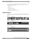
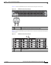
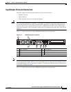
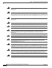
Figure 1-17 shows the location of the CDE100 back panel ports and connectors.
Figure 1-17 CDE100 Connector Locations
Note The system software does not support the use of a keyboard or mouse [Personal System 2 (PS/2) or
Universal Serial Bus (USB)]. However, the keyboard and mouse are supported by the BIOS for POST,
and the BIOS Setup Utility as described in
Chapter 4, “Installing the Internet Streamer CDS Software
and Initially Configuring a CDE.”
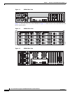
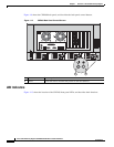
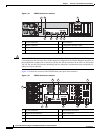
Figure 1-18 shows the location of the CDE200 back panel ports and connectors.
1 Power connector 5 VGA interface
2 Mouse connector 6 Management interface (eth0)
3 Keyboard connector 7 Ingest interface (eth1)
4 Serial console interface
211770
4 5
1 2
3 6 7