


D-5
Cisco Content Delivery Engine 100/200/300/400 Hardware Installation Guide
OL-13478-03
Appendix D Connecting DC Power
Connecting DC Power to a CDE300
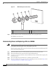
Step 6 Reconnect the +Return (red) and –48 VDC (black) DC power wires to your power source.
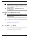
Connecting DC Power to a CDE300
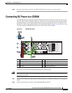
The CDE300 ships fully populated with three DC PMs installed in the PM slots on the rear of the chassis;
three DC power cables are shipped separately. The chassis has one ground stud that provides building
and PM grounding. The minimum cabling requirement for connecting DC power to a CDE300 is two
PM connects, but it is recommended that you use all three PM connects.
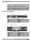
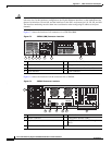
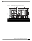
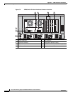
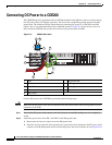
Figure D-5 shows the rear view
of a fully-connected CDE300 and provides the location of the studs and PMs.
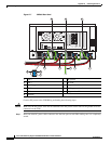
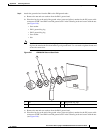
Figure D-5 CDE300 Rear Panel
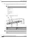
Connect DC power to the CDE300 by performing the following steps:
Caution Make sure the DC power wires are not attached to the DC power source until all the ground wires are
connected on the CDE.
Step 1 Insert one blue DC power cable connector into the blue port on each PM, making sure it is completely
seated.
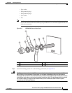
Step 2 Remove the nut and star washers from the Building/PM ground stud.
1 PM 1 5 +Return
2 PM 2 6 PM ground
3 PM 3 7 Building/PM ground stud
4 –48 VDC 8 Building ground wire
280160
1
2
3
4 5
6
7
8