


3-6
Cisco Content Delivery Engine 100/200/300/400 Hardware Installation Guide
OL-13478-03
Chapter 3 Installing the Content Delivery Engines
Installing the CDEs
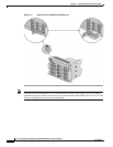
Connecting Power Cords
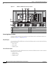
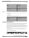
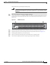
Redundant power connectors are located at the rear of the chassis as shown in Figure 3-2 through
Figure 3-5. Power connections have the following properties:
• Chassis power inlets accept AC (120V or 220V) or –48 VDC.
• The CDE100 chassis contains one VAC power port; the CDE200 chassis contains two VAC or VDC
power ports; the CDE300 chassis contains three VAC or VDC power ports, and the CDE400 chassis
contains four VAC or VDC power ports. See
Appendix D for information connecting DC Power.
Note All unlabeled ports are unused ports. Do not install cables in any unused ports.
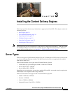
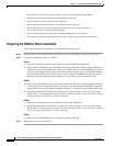
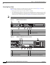
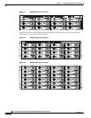
Figure 3-1 CDE100 Connector Locations
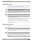
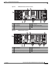
Figure 3-2 CDE200 or CDE200 ISV Connector Locations
1 Power connector 5 VGA interface
2 Mouse connector 6 Management interface (eth0)
3 Keyboard connector 7 Ingest interface (eth1)
4 Serial console interface
211770
4 5
1 2
3 6 7
1 Power connectors 5 VGA interface
2 Mouse connector 6 Management interface (eth0)
3 Keyboard connector 7 Ingest interface (eth1)
4 Serial console interface 8 Stream interfaces (eth2 through eth5)
211771
3 4 5 6 7
2
1
eth4
eth4
eth2
eth2
eth5
eth5
eth3
eth3
8
eth0 eth1