


B-2
Cisco Content Delivery Engine 100/200/300/400 Hardware Installation Guide
OL-13478-03
Appendix B Connector Pin Assignments
Ethernet Connector Pin Assignments
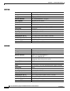
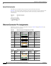
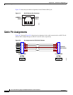
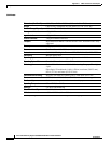
Serial Port Connector
The CDEs have one standard serial port connector located on the back of the device.
Figure B-1 shows the pin number assignments for the 9-pin, male D-shell serial port connector on the
back of the device. These pin number assignments conform to the industry standard for RS-232
communications.
Figure B-1 Serial Port Connector
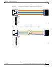
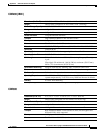
Ethernet Connector Pin Assignments
The Ethernet connector is an 8-pin, modular RJ-45 connector. Table B-2 through Table B-4 list the
Ethernet connector pin assignments.
1
5
69
83193
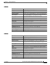
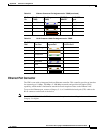
Table B-2 Ethernet Connector Pin Assignments for T568A
RJ-45
Pin
Wire Color
(T568A)
Wire Diagram
(T568A)
10BASE-T
100BASE-T
1000BASE-T
Signal
1 White/Green Transmit+ BI_DA+
2 Green Transmit– BI_DA–
3 White/Orange Receive+ BI_DB+
4Blue UnusedBI_DC+
5 White/Blue Unused BI_DC–
6 Orange Receive– BI_DB–
7 White/Brown Unused BI_DD+
8 Brown Unused BI_DD–
Table B-3 Ethernet Connector Pin Assignments for T568B
RJ-45
Pin
Wire Color
(T568B)
Wire Diagram
(T568B)
10BASE-T
100BASE-T
1000BASE-T
Signal
1 White/Orange Transmit+ BI_DA+
2 Orange Transmit– BI_DA–
3 White/Green Receive+ BI_DB+
4Blue UnusedBI_DC+