


3-8
Cisco Content Delivery Engine 100/200/300/400 Hardware Installation Guide
OL-13478-03
Chapter 3 Installing the Content Delivery Engines
Installing the CDEs
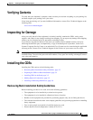
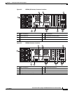
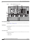
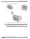
Figure 3-5 CDE400 or CDE400 ISV Connector Locations
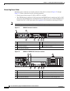
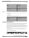
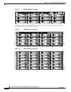
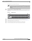
Connecting Network Cables
Using the topology prescribed for the application, attach Ethernet cables to the Ethernet interfaces on
the CDEs (see
Figure 3-1 through Figure 3-5).
SE and SR System
In a system that uses SEs and SRs that are collocated, the Ethernet cables are used to make the following
physical connections:
• SR to switch
• SE to switch
• CDSM to switch
Vault and Streamer System
In a system that uses Vaults and Streamers that are collocated, the Ethernet cables are used to make the
following physical connections:
• Vault to switch
• Streamer to switch
• CDSM to switch
1 Power connectors 5 VGA interface
2 Mouse connector 6 Management Interface (eth0)
3 Keyboard connector 7 Ingest Interface (eth1)
4 Serial console interface 8 Cache/Stream interfaces (eth2 through eth7)
270604
eth0 eth1
eth2
eth3
eth4
eth5
eth6
eth7
54 6 7
1
2
3
8