


C-6
Cisco Content Delivery Engine 100/200/300/400 Hardware Installation Guide
OL-13478-03
Appendix C CDEs with Serverworks Chipset
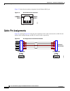
Connector Pin Assignments
Caution In some CDE200 chassis, the streaming interface NICs are installed in slots 4 and 5 (counting from the
left-most slot). In this hardware configuration, the Gigabit Ethernet interfaces on the motherboard are
detected as interfaces 3/0 and 4/0, and the interfaces on the NICs are detected as 1/0, 2/0, 5/0, and 6/0.
The interface numbering must be taken into consideration when configuring IP addresses and port
channels.
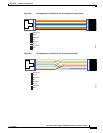
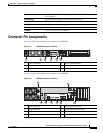
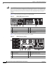
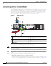
Figure C-3 shows the location of all connectors for a CDE200 (IBM).
Figure C-3 CDE200 (IBM) Connector Locations
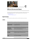
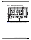
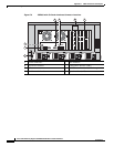
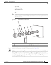
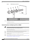
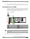
Figure C-4 shows the location of all the connectors for a CDE300.
Figure C-4 CDE300 Connector Locations
.
1 Serial console interface 5 Ingest Interface (eth2)
2 Mouse connector 6 Management Interface (eth0)
3 Keyboard connector 7 Stream interfaces (eth3, eth4, eth5)
4 VGA interface 8 Power connector
270613
eth2 eth3
eth4 eth5
1
PCI
2
PCI
3
PCI
4
PCI
AC
DC
AC
DC
eth0
43 6
87
51 2
1 Power connectors 5 VGA interface
2 Mouse connector 6 Management interface (eth0)
3 Keyboard connector 7 Cache/Stream interfaces (eth2 through
eth13)
4 Serial console interface
270610
eth11 eth7
eth10
eth9
eth8 eth6
eth5
eth4
eth3
eth2
eth13
eth12
3
2
eth1eth0
4 5 6
1
7