


1-6
Cisco Aironet 1300 Series Wireless Outdoor Access Point/Bridge Hardware Installation Guide
OL-5048-06
Chapter 1 Overview
Key Features
Ethernet Ports
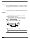
The access point/bridge dual-coax Ethernet ports consists of a pair of 75-ohm F-type connectors, linking
the unit to your 100BASE-T Ethernet LAN through the power injector. The dual-coax cables are used to
send and receive Ethernet data and to supply inline 48-VDC power from the power injector to the access
point/bridge. For the location of the ports, refer to Figure 1-3.
Enclosure
The access point/bridge uses an enclosure that supports indoor or outdoor operating environments. (refer
to “Access Point Specifications” section on page C-1).
Connectors
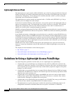
The connectors (see Figure 1-2) provided depend upon the access point/bridge configuration:
• Integrated antenna access point/bridge configuration
–
Dual-coax Ethernet connectors—used to provide Ethernet signals and in-line power
• External antenna access point/bridge configuration
–
Dual-coax Ethernet connectors—used to provide Ethernet signals and in-line power
–
Dual antenna connectors—used to support a single antenna or dual-diversity antennas
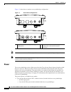
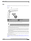
Figure 1-2 Access Point Connector Locations
1 Ground lug mounting screws 3 Mounting posts
2 Left antenna connector (external antenna
access point/bridge configuration only)
4 LEDs
Primary right antenna connector (external
antenna access point/bridge configuration
only)
5 Dual-coax Ethernet ports (F-Type connectors)
117060
1
2
3
4
5