


2-7
Cisco Aironet 1300 Series Wireless Outdoor Access Point/Bridge Hardware Installation Guide
OL-5048-06
Chapter 2 Installation Overview
Before Beginning the Installation
Note The external antenna access point/bridge configuration does not ship with an external antenna. An
external antenna must be purchased.
The optional roof mount kit contains these items:
• One roof-wall mount
• Two dual-coax cables [20 ft (6.1 m) and 50 ft (15.2 m)]
• Multi-function mount (consisting of a access point/bridge bracket and a mast bracket)
• Two tower clamps (U-bolts) with four nuts and washers
• Four bolts and washers for securing the access point/bridge bracket to the mast bracket
• Four bolts for securing the access point/bridge bracket to the unit
• Grounding block and mounting screws
• Ground lug for the access point/bridge, two hex nuts, and two washers
• Weatherproofing kit (consisting of Coax Seal and electrical joint compound)
The optional wall mount kit (for indoor use) contains these items:
• Wall mount bracket with 4 mounting bolts and washers
• Two sub-mini RG-59 coax cables (12 in. or 30.5 cm)
The optional transportation power injector
• Power injector (LR2T) unit
Before Beginning the Installation
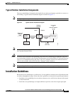
Before you begin the installation process, please carefully review the following list of figures to become
familiar with the system components, connectors, indicators, cables, system interconnection, and
grounding:
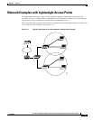
• Installation diagram (Figure 2-1)
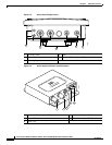
• Access point/bridge layout (Figure 2-2)
• Power injector layout (Figure 2-3)
• Power module (Figure 2-4)
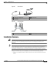
• Grounding block (Figure 2-5)
Note To meet regulatory restrictions, the external antenna access point/bridge unit and the external antenna
must be professionally installed. The network administration or other IT professional responsible for
installing and configuring the unit is a suitable professional installer. Following installation, access to the
unit should be password-protected by the network administrator to maintain regulatory compliance.