2-13
Cisco AC/DC Power System User Guide, R1.0
May 2006
Chapter 2 System Installation
2.3 Install AC Power Cables
–
International Electromechanical Commission (IEC)
–
Any local or site specific codes
–
EN60950
Warning
Installation of the equipment must comply with local and national electrical codes.
Statement 1074
• Never install damaged or malfunctioning equipment.
To install AC power to the Cisco AC/DC Power System:
Step 1 Ensure that input circuit breakers or fuses are off or removed and the cable is not connected to the outlet.
Step 2 To aid in future expansion, all AC cable positions should be connected to the rear of the shelf during
installation.
Step 3 The system shelf is supplied with four AC cables. Each AC cable provides power to individual rectifier
positions. The cable is terminated to allow for local plug requirements.
Note A 15A circuit (for both 110 and 208V AC) should be used based on maximum AC input per
rectifier (9.1A).
Step 4 The rear system shelf cover should already be removed, if not, remove it.
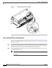
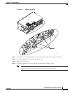
Step 5 Locate the cables at the rear of the system shelf.
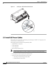
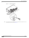
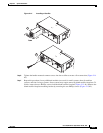
Step 6 Attach the ferrule end of the cables (Ground (G), L1, and L2 (neutral) to the system shelf AC receptacle
by inserting (the ferrule will only fit in one direction) and tightening with a flat screwdriver
(Figure 2-12).


