


2-23
Cisco AC/DC Power System User Guide, R1.0
May 2006
Chapter 2 System Installation
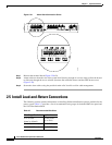
2.4.1 Install the Alarm Cable
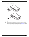
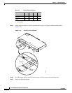
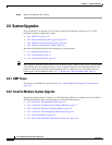
Figure 2-20 Installing an Alarm Cable
Step 4
Alarm contacts labeled 1 through 4, NO, C, and NC refer to the OFF state of the power system and
alarmed condition (Table 2-6).
Note Either NO or NC can be used for alarming. Figure 2-20 depicts the NC connection in the 1 and
3 positions on the connectors.
Step 5 The terminal blocks (green) will accept 26AWG (0.14mm²) to 22AWG (0.34mm²) cables. Remove the
terminal block (Figure 2-20 #1).
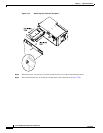
Step 6 Insert the stripped alarm cables and tighten using a flat screwdriver (Figure 2-20 #2). Refer to
Figure 2-21 (Version 2 of the controller) and Figure 3-4 on page 3-5 (Version 1 of the controller) for
information on alarm connection locations.
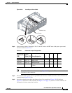
Table 2-6 Alarm and Jumper Designations
Jumper
(System with
LCD)
Jumper
(System
without LCD) Alarm Designation 1234
J16 (1-3) J16 (1-3) Low Voltage X
J15 (1-3) J15 (1-3) Mains Error X
J14 (1-3) J14 (1-3) Module Failure X
J14 (4-6) J13 (1-3) Fuse/Circuit Breaker
Failure
X
124795
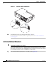
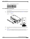
Service Loop
Tie-off Points