


5-3
Cisco AC/DC Power System User Guide, R1.0
May 2006
Chapter 5 System Troubleshooting
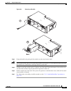
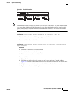
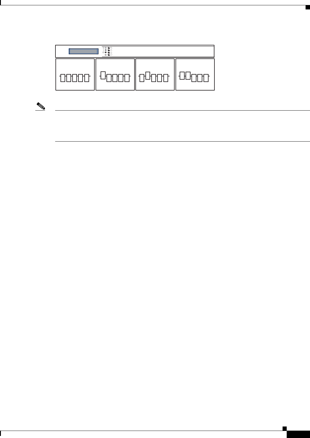
Figure 5-1 Module Locations
Note Sometimes the rectifier that indicates a failure is not the cause of the failure. The failure may be caused
by a current share imbalance. If the failure persists even after replacing the rectifiers showing a fault,
replace each rectifier in turn with a known good unit until the fault clears. The replaced module that
clears the fault is the defective one.
Error Message Urgent Module Failure (Red light on controller, Relay #3)
Explanation
More than one rectifier is reporting a module failure.
Recommended Action See module failure.
Error Message Communication Failure (Yellow light on controller, flashing yellow
light on module)
Explanation
1.
Controller is looking for the installed module
2. A module has been removed and not replaced
3. Broken or disconnected communication wire
Recommended Action
1.
Wait for 5 minutes.
2. Verify that the module address is properly set and is not a duplicate of another address
(Figure 5-1). Rectifier address DIP switches are located at the inside rear of the rectifier shelf.
3. Verify that the communication cable at the back of the rectifier shelf is connected.
4. Replace communication cable if required.
124816 124816 124816 124816
124777