


Chapter 2 Installation
Optional Installation Steps
2-14
Cisco 1760 Modular Access Router Hardware Installation Guide
78-13342-03
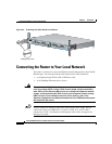
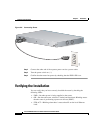
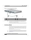
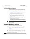
Figure 2-9 Connecting the Console Cable to the Router
Step 2 Connect the end of the cable with the DB-9 connector to the terminal or PC. If
your terminal or PC has a console port that does not fit a DB-9 connector, you
must provide a correct adapter for that port.
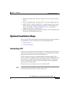
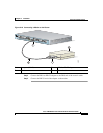
Connecting a Modem
When a modem is connected to the auxiliary port, a remote user can dial into the
router and configure it. You can use the light blue console cable that came in the
accessory kit. If you are using the light blue cable with the console port, you can
use any crossover RJ-45-to-RJ-45 cable, along with an RJ-45-to-DB-25 adapter
that you must provide.
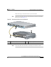
Follow these steps to connect a modem to the router:
Step 1 Connect the RJ-45 end of the console cable to the black AUX port on the router.
(See Figure 2-10.)
1 Blue console port 3 Light blue console cable
2 To PC or terminal
C
isco 1700
S
e
rie
s
10/100 E
THE
RN
ET
AUX
C
ONS
OLE
PVDM 0
OK
OK
PWR
1
0
SLOT 0
OK
PVDM 1
OK
MOD
OK
1
0
SLOT 1
OK
LINK
100
FDX
ACT
COL
10
SLOT 2
OK
1
0
SLOT 3
OK
1
3
2
60946