


2
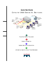
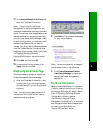
Cable the Switch
1x
MODE
3x
4x
5x
6x
7x
8x
1x
2x
9x
10x
11x
12x
13x
14x
15x
16x
17x
18x
19x
20x
21x
22x
23x
24x
10BaseT/100BaseTX
1x
2x
3x
4x
1X
100BaseFX
1X
100BaseFX
RJ-45-to-RJ-45
Cat 5 straight-
through cable
RJ-45
Ethernet port
RJ-45
10/100 port
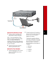
WS-X2914-XL-V
Tighten
Screws
To Activate
WS-X2922-XL-V
Tighten
Screws
To Activate
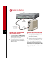
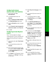
Connect PCs, Workstations,
Servers, and Routers
1
Connect a Category 5 straight-through
cable (not supplied) to a 10/100 port on
the front panel of the switch.
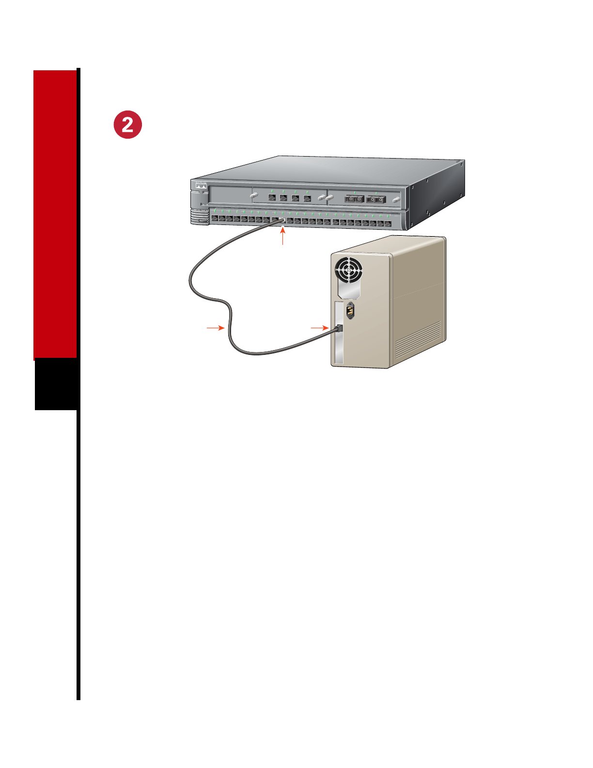
2
Connect the other end of the cable to
the RJ-45 port of the PC, workstation,
server, or router.
Connect Switches and Hubs
1
Connect a Category 5 crossover cable
(not supplied) to a 10/100 port on the
front panel of the switch.
2
Connect the other end of the cable to an
RJ-45 port of the target switch or hub.
Note: Use a straight-through cable to
connect two ports when one of the ports is
designated with an X. Use a crossover cable
to connect two ports when both ports are
designated with an X.