


1-9
Cisco IE 3010 Switch Hardware Installation Guide
78-19581-02
Chapter 1 Product Overview
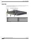
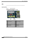
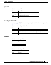
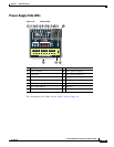
Cable Side
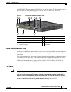
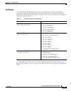
System LED
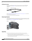
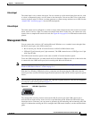
Power-Supply Module LEDs
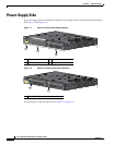
The switch power-supply module LEDs are labeled PSU1 and PSU2 (on the switch) and PSU OK (on
the power-supply module). They show whether power-supply modules 1 and 2 are receiving power. See
Figure 1-6 and Figure 1-9.
Alarm LEDs
Table 1-3 System LED
Color System Status
Off System is not powered on.
Blinking green POST
1
is in progress.
1. POST = power-on self-test.
Green System is operating normally.
Amber System is receiving power but is not functioning properly.
Table 1-4 Power-Supply Module LEDs
Color System Status
Off Power-supply module (1 or 2) is not installed.
Green Valid input is present, and the output is within the operating range.
Red Valid input is present, and the output is outside the operating range or is not present.
Blinking red Valid input is not present.
Table 1-5 Alarm Input LEDs
Color System Status
Off No alarm
Amber Minor alarm
Red Major alarm
Blinking red Critical alarm
Table 1-6 Alarm Output LED
Color System Status
Green No alarm
Red Relay closed, alarm present