


2-15
Cisco IE 3010 Switch Hardware Installation Guide
78-19581-02
Chapter 2 Switch Installation
Installing the Switch
After the switch is mounted in the rack:
• Wire the switch to a power source. See Chapter 3, “Power Supply Installation.”
• Connect the ports. See the “Connecting Devices to the Ethernet Ports” section on page 2-25.
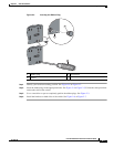
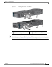
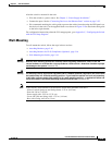
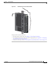
• We recommend attaching the cable guide to prevent the cables from obscuring the LED panels on
the devices in the rack. Use the supplied black screw shown in Figure 2-10 to attach the cable guide
to the left or right bracket.
For configuration instructions about the CLI setup program, go to Appendix C, “Configuring the Switch
with the CLI Setup Program.”
Wall-Mounting
To wall-mount the switch, follow the steps in these sections:
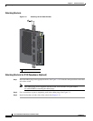
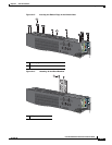
• Attaching Brackets, page 2-16
• Attaching Brackets for IP-30 Compliance (Optional), page 2-16
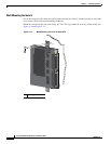
• Wall-Mounting the Switch, page 2-18
Warning
Read the wall-mounting instructions carefully before beginning installation. Failure to use the
correct hardware or to follow the correct procedures could result in a hazardous situation to people
and damage to the system.
Statement 378
Warning
For mounting railway-application equipment and for EN50155 standard compliance, the switch must
be installed only in a rack mid-mounting position. If you install the switch in a front rack-mounting
(cable side or power supply side) position or in a wall-mounting position, a mechanical failure can
occur that results in the switch becoming detached from the rack.
Statement 403
Note If the switch is wall-mounted in an enclosure, follow these minimum clearances:
- Sides of switch (facing up and facing down): 3.75 in. (9.52 cm)
- Port side 3.0 in. (7.62 cm)
- Power supply side: 5.25 in. (13.33 cm)
- Cover side (side not facing wall): 1.75 in. (4.44 cm)
- Base side (facing wall): 0 in. (0 cm)