


3-12
Cisco IE 3010 Switch Hardware Installation Guide
78-19581-02
Chapter 3 Power Supply Installation
Removing the Power-Supply Module
Step 8 Torque the captive screws (above the wires) to 8.5 in-lb (± 0.5 in-lb).
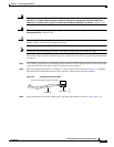
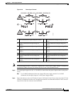
Step 9 AC power
Connect the other end of the line wire (the one connected to L) to the line terminal on the AC-power
source, and connect the other end of the neutral wire (the one connected to N) to the neutral terminal on
the AC power source.
DC power
Connect the other end of the positive wire (the one connected to +) to the positive terminal on the
DC-power source, and connect the other end of the negative wire (the one connected
to –) to the negative terminal on the DC power source.
Step 10 Close the power-input terminal cover. Use a ratcheting torque screwdriver to torque the screw to 6–8
in-lb.
Step 11 Turn on the power at the AC or DC circuit, verify that the PSU1 or PSU2 LED on the switch and PSU
OK LED on the power-supply module are green.
Step 12 If you have two power supplies, repeat Step 1 through Step 11. See the switch software guide for
information on how to configure the power supply settings.
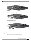
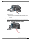
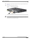
Removing the Power-Supply Module
The power-supply modules are hot-swappable. By removing the power-supply modules, you can power
off the switch without disconnecting the wiring from the power-input terminal.
Step 1 We recommend that power be OFF at the AC or DC circuits. Locate the circuit breakers, turn them OFF
and tape them in the OFF position.
Note If the power is not off at the AC or DC circuit breaker, do not touch the power-input terminal.
Step 2 Verify that the PSU LED and PSU OK LED is blinking red or is off.
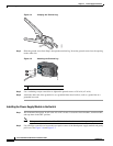
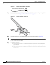
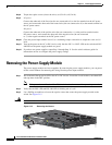
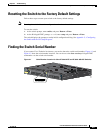
Step 3 Use a Phillips screwdriver to loosen the captive screws that secure the power-supply module to the
switch. See Figure 3-15.
Warning
Hot surface.
Statement 1079
Figure 3-15 Removing the Screws
Cisco IE 3010
Switch Series
208384