


1-6
Catalyst 3550 Switch Hardware Installation Guide
OL-6155-01
Chapter 1 Product Overview
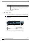
Front-Panel Description
GBIC Module Slots
You cannot configure speed or duplex mode on GBIC slots, but for certain types of GBICs, you can
configure speed to not negotiate (nonegotiate) if connected to a device that does not support
autonegotiation.
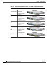
The GBIC module slots support these modules to provide flexibility in media and distance options:
• 1000BASE-T GBIC module for copper connections of up to 328 feet (100 meters).
• 1000BASE-SX GBIC module for fiber-optic connections of up to 1,804 feet (550 meters)
multimode only.
• 1000BASE-LX/LH GBIC module for fiber-optic connections of up to 32,810 feet (10 kilometers)
single mode or 1,804 feet (550 meters) multimode.
• 1000BASE-ZX GBIC module for fiber-optic connections of up to 328,000 feet (100 kilometers)
single mode only.
• GigaStack GBIC module for creating a 1-Gbps stack configuration of up to nine supported switches.
The GigaStack GBIC supports one full-duplex link (in a point-to-point configuration) or up to nine
half-duplex links (in a stack configuration) to other Gigabit Ethernet devices. When you use the
required Cisco proprietary signaling and cabling, the maximum distance for a GigaStack
GBIC-to-GigaStack GBIC connection is 3 feet (1 meter).
• Coarse Wave Division Multiplexing (CWDM) GBIC modules for fiber-optic connections of up to
393,719 feet (120 kilometers) single mode only.
Cisco-approved CWDM GBIC modules have a serial EEPROM that contains the module serial
number, the vendor name and vendor ID, a unique security code, and cyclic redundancy check
(CRC). When a CWDM GBIC module is inserted in the switch, the switch software reads the
EEPROM to check the serial number, vendor name and vendor ID, and recompute the security code
and CRC. If the serial number, the vendor name or vendor ID, the security code, or CRC is invalid,
the switch places the port in an error-disabled state.
For more information about GBICs, see the documentation included with your GBIC module and
Related Publications, page xiii, for a list of related documentation.
LEDs
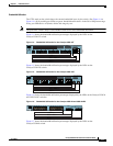
You can use the switch LEDs to monitor switch activity and its performance. Figure 1-3 shows the LEDs
and the Mode button that you use to select one of the port modes.
All of the LEDs described in this section except the utilization meter (UTIL) are visible on the device
manager and through the Network Assistant.
System LED
The system LED shows whether the system is receiving power and is functioning properly. Table 1-2
lists the LED colors and their meanings.
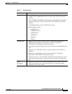
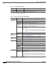
Table 1-2 System LED
Color System Status
Off System is not powered on.