


B-2
Catalyst 3550 Multilayer Switch Hardware Installation Guide
OL-6155-01
Appendix B Connector and Cable Specifications
Connector Specifications
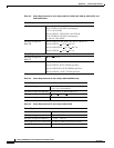
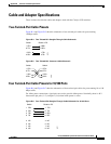
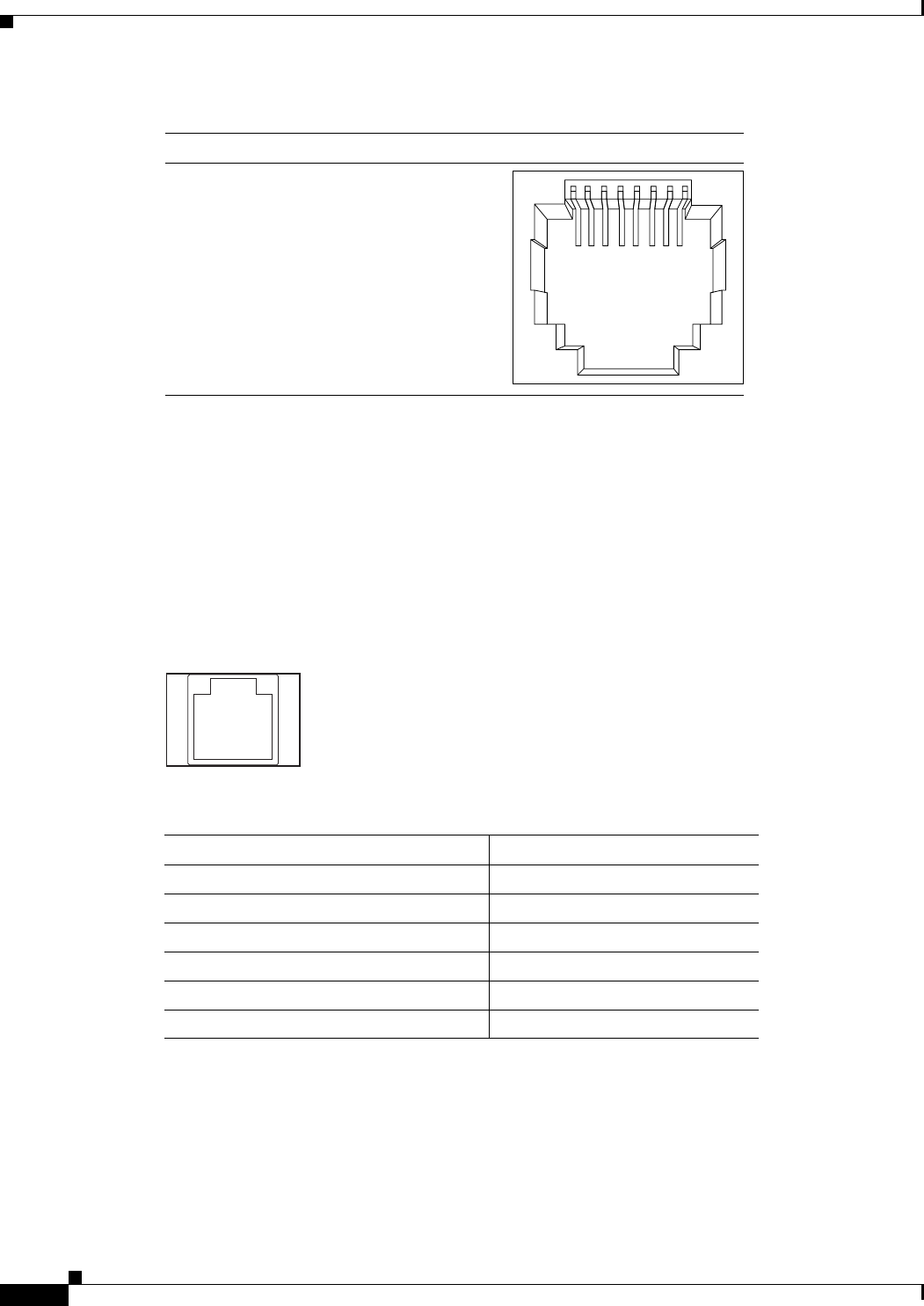
Figure B-2 10/100/1000 Port Pinouts
100BASE-FX Ports
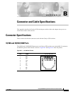
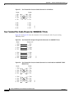
The 100BASE-FX ports use MT-RJ connectors, as shown in Figure B-3. The 100BASE-FX ports use
50/125- or 62.5/125-micron multimode fiber-optic cabling.
You can connect a 100BASE-FX port to an SC or ST port on a target device by using one of the MT-RJ
fiber-optic patch cables listed in Table B-1. Use the Cisco part numbers in Table B-1 to order the patch
cables that you need.
Figure B-3 MT-RJ Connector
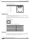
Console Port
The console port uses an 8-pin RJ-45 connector, described in Table B-2 and Table B-3. The supplied
RJ-45-to-DB-9 adapter cable is used to connect the console port of the switch to a console PC. For
console port and adapter pinout information, see Table B-2 and Table B-3.
60915
231 45678Pin Label
1
2
3
4
5
6
7
8
TP0+
TP0-
TP1+
TP2+
TP2-
TP1-
TP3+
TP3-
Table B-1 MT-RJ Patch Cables for 100BASE-FX Connections
Type Cisco Part Number
1-meter, MT-RJ-to-SC multimode cable CAB-MTRJ-SC-MM-1M
3-meter, MT-RJ-to-SC multimode cable CAB-MTRJ-SC-MM-3M
5-meter, MT-RJ-to-SC multimode cable CAB-MTRJ-SC-MM-5M
1-meter, MT-RJ-to-ST multimode cable CAB-MTRJ-ST-MM-1M
3-meter, MT-RJ-to-ST multimode cable CAB-MTRJ-ST-MM-3M
5-meter, MT-RJ-to-ST multimode cable CAB-MTRJ-ST-MM-5M
28845