


2-17
Catalyst 3550 Switch Hardware Installation Guide
OL-6155-01
Chapter 2 Switch Installation
Powering the Switch and Connecting Devices
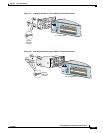
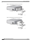
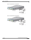
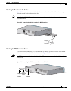
Connecting a Cisco RPS
Use the cable supplied with the RPS to connect to the switch rear panel. Connect the switch and the RPS
to the same AC power source. Always put the RPS in standby mode when you connect devices to it and
in active mode during normal operation.
Note Make sure to connect the switch and the RPS to the same AC power source.
You can connect the Cisco RPS 300 (model PWR300-AC-RPS-N1) to these switch models:
• Catalyst 3550-12T, 3550-12G, 3550-24, 3550-FX, or 3550-48 switch. (The Cisco RPS 300 does not
support the Catalyst 3550-24-DC or 3550-24PWR switch.)
Warning
Attach only the Cisco RPS (model PWR300-AC-RPS-N1) to the RPS receptacle.
Statement 100B
You can connect the Cisco RPS 675 (model PWR675-AC-RPS-N1) to these switch models.
• Catalyst 3550-12T, 3550-12G, 3550-24, 3550-FX, 3550-24PWR, or 3550-48 switch. (The Cisco
RPS 675 does not support the Catalyst 3550-24-DC switch.)
Warning
Attach only the Cisco RPS (model PWR675-AC-RPS-N1) to the RPS receptacle.
Statement 100C
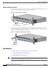
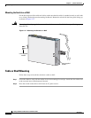
Connecting to the 10/100 and 10/100/1000 Ports
Caution To prevent ESD damage, follow your normal board and component handling procedures when
connecting to the Ethernet ports.
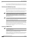
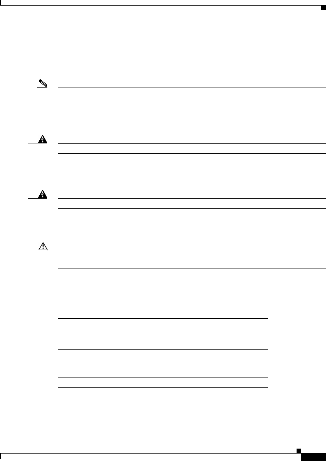
Use the guidelines in Table 2-1 to select the correct cable for connecting the switch 10/100 and
10/100/1000 ports to other devices. See the “Cable and Adapter Specifications” section on page B-3 for
cable-pinout descriptions.
Table 2-1 Recommended Ethernet Cables
Device Crossover Cable
1
1. 100BASE-TX and 1000BASE-T traffic requires twisted four-pair, Category 5 cable. 10BASE-T
traffic can use Category 3 or Category 4 cable.
Straight-Through Cable
1
Switch to switch Yes No
Switch to hub Yes No
Switch to computer
or server
No Yes
Switch to router No Yes
Switch to IP phone No Yes