


C-5
Catalyst 3550 Multilayer Switch Hardware Installation Guide
OL-6155-01
Appendix C DC Power Connections
Connecting to DC Power
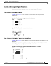
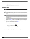
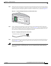
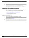
Step 2 Identify the positive and negative feed positions for the terminal block connection. The wiring sequence
is positive to positive and negative to negative for both the A and the B feed wires. The switch rear panel
identifies the positive and negative positions for both the A and B feed wires, as shown in Figure C-5.
Figure C-5 Positive and Negative Positions on the Switch Rear Panel
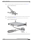
Step 3
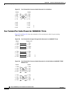
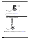
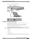
Using a 18-gauge wire-stripping tool, strip each of the four wires coming from the DC-input power
source to 0.27 inch (6.6 mm) ± 0.02 inch (0.5 mm), as shown in Figure C-6. Do not strip more than 0.29
inch (7.4 mm) of insulation from the wire. Stripping more than the recommended amount of wire can
leave exposed wire from the terminal block plug after installation.
Figure C-6 Stripping the DC-Input Power Source Wire
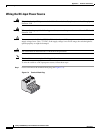
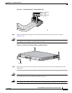
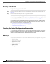
Step 4
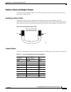
Insert the exposed wire of one of the four DC-input power source wires into the terminal block plug, as
shown in Figure C-7. Make sure that you cannot see any wire lead. Only wire with insulation should
extend from the terminal block.
Warning
An exposed wire lead from a DC-input power source can conduct harmful levels of electricity. Be sure
that no exposed portion of the DC-input power source wire extends from the terminal block plug.
Statement 122
74626
INPUT -36 - -72 V
CURRENT: 2 - 1A
A
B
0.25 inch (6.3 mm)
±
0.02 inch (0.5 mm)
86460