


1-9
Catalyst 3550 Switch Hardware Installation Guide
OL-6155-01
Chapter 1 Product Overview
Front-Panel Description
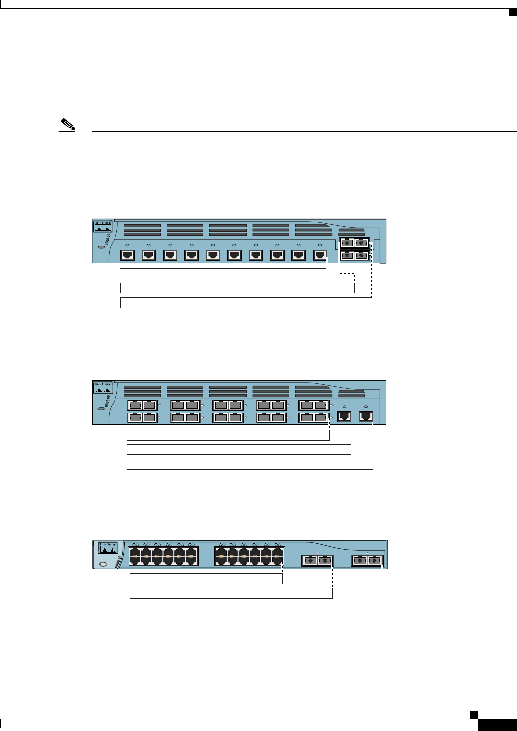
Bandwidth Utilization
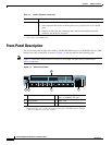
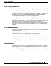
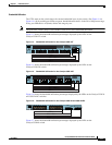
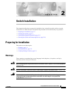
The UTIL mode on the switch shows the current bandwidth in use by the switch. (See Figure 1-4 to
Figure 1-8.) If all possible port LEDs are green, bandwidth utilization is in the 50 to 100 percent range.
Every port LED that is off (black) divides this range by two.
Note The port LEDs on the Catalyst 3550-24PWR switch do not show bandwidth utilization.
Figure 1-4 shows the bandwidth utilization percentages displayed by the LEDs on the
Catalyst 3550-12T switch.
Figure 1-4 Bandwidth Utilization for the Catalyst 3550-12T
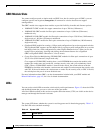
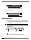
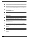
Figure 1-5 shows the bandwidth utilization percentages displayed by the LEDs on the
Catalyst 3550-12G switch.
Figure 1-5 Bandwidth Utilization for the Catalyst 3550-12G
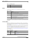
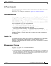
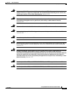
Figure 1-6 shows the bandwidth utilization percentages displayed by the LEDs on the Catalyst 3550-24
and 3550-24-DC switches.
Figure 1-6 Bandwidth Utilization for the Catalyst 3550-24 and 3550-24-DC
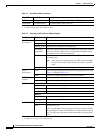
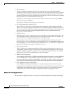
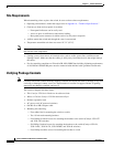
Figure 1-7 shows the bandwidth utilization percentages displayed by the LEDs on the
Catalyst 3550-48 switch.
74026
2
SPEED
SYSTEM
RPS
STATUS
MODE
UTIL
DUPLX
1
< 25% +
50% +
25% – 49% +
Catalyst 3550 SERIES
1
2
345
67
8910
SPEED
SYSTEM
RPS
STATUS
MODE
UTIL
DUPLX
74039
2
1
2
1
2
1
2
1
2
1
910
Catalyst 3550 SERIES
< 25% +
50% +
25% – 49% +
SPEED
SYSTEM
RPS
STATUS
MODE
UTIL
DUPLX
74023
2
Catalyst 3550 SERIES
1
1
1X
2X
11X
12X
13X
14X
15X
16X
2 3 4 5 6 7 8 9 10 1112 1314 1516 1718 1920 2122 2324
< 25% +
25% – 49% +
50% +