


2-12
Catalyst 3550 Switch Hardware Installation Guide
OL-6155-01
Chapter 2 Switch Installation
Installing the Switch
Mounting the Switch in a Rack
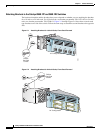
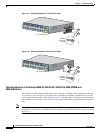
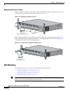
After the brackets are attached to the switch, use the four supplied number-12 Phillips machine screws
to securely attach the brackets to the rack, as shown in Figure 2-13.
Figure 2-13 Mounting the Switch in a Rack
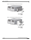
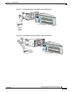
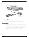
We recommend attaching the cable guide to prevent the cables from obscuring the front panel of the
switch and the other devices installed in the rack. Use the supplied black screw, as shown in Figure 2-14,
to attach the cable guide to the left or right bracket.
Figure 2-14 Attaching the Cable Guide on the Switch
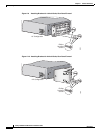
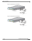
Wall Mounting
To install the switch on a wall, follow the instructions in these procedures:
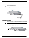
• Attaching the Brackets to the Switch, page 2-13
• Attaching the RPS Connector Cover, page 2-13
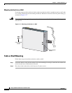
• Mounting the Switch on a Wall, page 2-14
Note The illustrations in this section show the Catalyst 3550-12T switch as an example. All the Catalyst 3550
switches are wall-mounted following the same procedures.
MODE
SYSTEM
R
PS
STATUS
UTIL
D
UPLX
SPEED
2
1
1
2
3
4
5
6
7
8
9
10
Catalyst 3550
SERIES
74033
Phillips machine screws
MODE
SYSTEM
RPS
STATUS
UTIL
DUPLX
SPEED
2
1
1
2
3
4
5
6
7
8
9
10
Catalyst 3550
SERIES
74034
Cable guide screw