


1-3
Catalyst 3750-E and Catalyst 3560-E Switch Hardware Installation Guide
OL-9774-03
Chapter 1 Product Overview
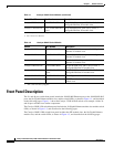
Front Panel Description
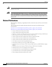
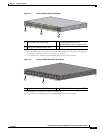
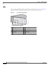
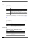
Figure 1-1 24- and 48-Port Switch Front Panel
158104
3
2
MODE
SYST
RPS
MASTR
STAT
DUPLX
SPEED
PoE
STACK
49
51
X2-1
X2-2
50
52
37
38
399
40
41
42
43
44
45
46
47
48
37X
47X
38X
48X
25
26
27
28
29
30
31
32
33
34
35
36
25X
35X
26X
36X
13
14
15
16
17
18
19
20
21
22
23
24
13X
23X
14X
24X
1
2
3
4
5
6
7
8
9
10
11
12
1X
11X
2X
12X
Catalyst 3750-E
SERIES
PoE-48
1
1 Mode button and switch LEDs 2 10/100/1000 Ethernet ports or
10/100/1000 PoE ports
1. Port numbering is from left to right, with port 1 on the far left. The first member of the pair (port 1) is above
the second member (port 2). On a 24-port switch, module slot numbers are 25, 26 upper, 27, 28 lower. On a
48-port switch, module slot numbers are 49, 50 upper, 51, 52, lower.
1
and port LEDs
3 10-Gigabit Ethernet module slots
2. For use with the Cisco TwinGig Converter Modules and Cisco X2 transceiver modules.
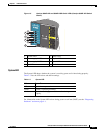
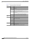
2
Figure 1-2 Catalyst 3560E-12D Switch Front Panel
X2-12
23
X2-11
21
X2-10
19
X2-9
17
X2-8
15
X2-7
13
X2-6
11
X2-5
9
X2-4
7
X2-3
5
X2-2
3
X2-1
1
24222018161412108642
PS1
PS2
FAN
STAT
DUPLEX
SPEED
MODE
SYST
202039
1
2
1 Mode button and switch LEDs 2 10-Gigabit Ethernet module slots
1,2,3
1. Port numbering is from left to right, with port 1 on the far left.
2. For use with the Cisco TwinGig Converter Modules and Cisco X2 transceiver modules.
3. Use a slotted screwdriver to remove the X2-slot EMC plugs.