


3-9
Catalyst 3750-E and Catalyst 3560-E Switch Hardware Installation Guide
OL-9774-03
Chapter 3 Power Supply and Fan Module Installation
Installing a DC-Power Supply
Wiring the DC-Input Power Source
To wire the DC-power-supply module to a DC-input power source, follow these steps.
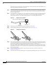
Step 1 Using a wire-stripping tool, strip each of the four wires coming from the DC-input power source to the
appropriate length for either the round eyelet or the fork-type terminals.
Step 2 Using a Panduit crimping tool, crimp the terminals to the 16-gauge DC-power input wires.
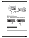
Step 3 Connect the DC-input power terminals to the terminal blocks as shown in Figure 3-10 or Figure 3-11.
Make sure to match the polarity (negative to negative, positive to positive) when connecting the wires to
the terminal blocks.
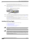
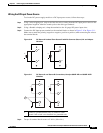
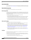
Figure 3-10 DC Source A Isolated From Source B with No Common Ground, 24- and 48-port
Switches
B+
157718
B-
+
A+
A-
+
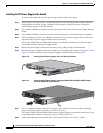
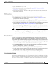
Figure 3-11 DC Source A and Source B Connections, Catalyst 3560E-12D and 3560E-12SD
Switches
B+
B-
-
+
A+
A-
-
+
202313
1
1 Connect to grounded metal rack, or connect to earth
ground if the switch is not installed in a grounded rack.
Step 4 Torque all terminal block screws to 5 lbf-in. (80 ozf-in.).