


3-10
Catalyst 3750-E and Catalyst 3560-E Switch Hardware Installation Guide
OL-9774-03
Chapter 3 Power Supply and Fan Module Installation
Installing a Fan Module
Step 5 Replace the terminal block plastic safety cover. For 24- and 48-port switches, torque the safety-cover
screw to 10
lbf-in. (160 ozf-in.).
Step 6 Move the DC-power source circuit-breaker handles to the ON position.
Step 7 For 24- and 48-port switches, confirm that the power-supply DC OK LED is green. See Table 1-12 for a
description of the module LEDs.
For Catalyst 3560E-12D and 3560E-12SD switches, confirm that the power-supply Input OK LED is
green. See
Table 1-14 for a description of the power supply LEDs.
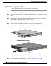
Installing a Fan Module
To remove and install a fan module, follow these steps:
Step 1 For 24- and 48-port switches, use a number-2 Phillips screwdriver to loosen the two captive screws that
secure the fan module to the switch chassis.
Caution You should replace the fan module within 2 minutes to avoid overheating the switch.
Step 2 For 24- and 48-port switches, remove the fan module by pulling on the extraction handle.
For Catalyst 3560E-12D and 3560E-12SD switches, remove the fan module by pinching and then pulling
the extraction handle.
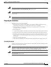
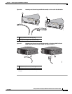
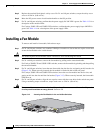
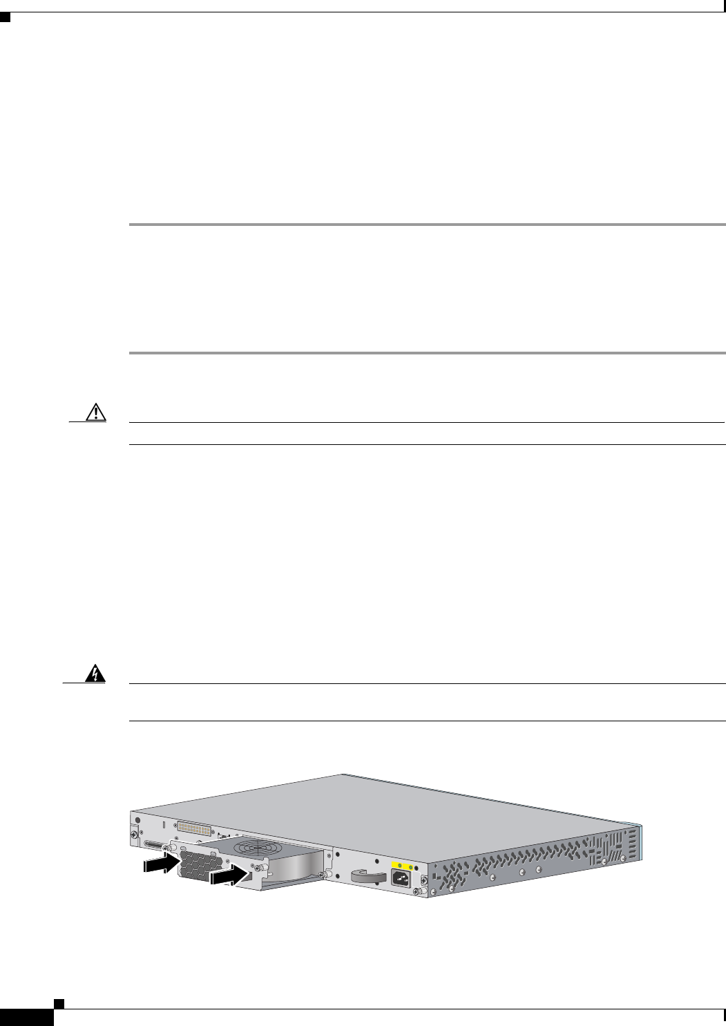
Step 3 For 24- and 48-port switches, insert the new fan module into the fan slot, and gently push it into the slot
(
Figure 3-12). When correctly inserted, the fan module is flush with the switch rear panel.
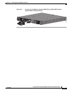
For Catalyst 3560E-12D and 3560E-12SD switches, insert the new fan module into the fan slot, and
gently push it into the slot until the fan latches (
Figure 3-13). When correctly inserted, the fan module
LED turns on.
Step 4 For 24- and 48-port switches, align the two captive screws with the screw holes in the switch rear panel.
Using a ratcheting torque screwdriver, torque each screw to 5 lbf-in. (80 ozf-in.).
Warning
Do not reach into a vacant slot or chassis while you install or remove a module or a fan. Exposed
circuitry could constitute an energy hazard.
Statement 206
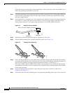
Figure 3-12 Inserting the Fan Module in 24- and 48-Port Switches
200101
AC OK PS OK
100-240V
~
1.0-5A
50-60 H
Z