


2-6
Catalyst 3750-E and Catalyst 3560-E Switch Hardware Installation Guide
OL-9774-03
Chapter 2 Switch Installation
Planning a Switch Stack (Catalyst 3750-E Switches)
Planning a Switch Stack (Catalyst 3750-E Switches)
If you plan to stack your switches, read these sections:
• Switch Stacking Guidelines, page 2-6
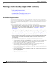
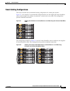
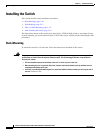
• Stack Cabling Configurations, page 2-7
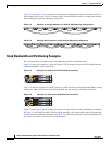
• Stack Bandwidth and Partitioning Examples, page 2-8
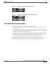
• Power On Sequence for Switch Stacks, page 2-9
Switch Stacking Guidelines
For general concepts and procedures to manage switch stacks, see the switch software configuration
guide on Cisco.com. When adding a Catalyst
3750-E switch to an existing 3750 switch stack, review the
Catalyst 3750-E Switch Stack Compatibility Guide on Cisco.com for information about mixed stack
configurations.
Before connecting the switches in a stack, keep in mind these stacking guidelines:
• Size of the switch and any optional power-supply module. The 1150-W power-supply module is
longer than the other modules. Stacking switches with the same power-supply modules together
makes it easier to cable the switches. For switch dimensions, see
Appendix A, “Technical
Specifications.”
• Length of cable. Depending on the configurations that you have, you might need different sized
cables. If you do not specify the length of the StackWise cable, the 0.5-meter cable is supplied. If
you need the 1-meter cable or the 3-meter cable, you can order it from your Cisco supplier. For cable
part numbers, see the
“StackWise Ports” section on page 1-14. The “Stack Cabling Configurations”
section on page 2-7 provides examples of recommended configurations.
• Access to the switch rear panel and to the rear of the rack if you are planning to stack the switches.
If you do not have access to the rear panel, make sure that you cable the switches before you
rack-mount them.
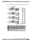
• For switch stacks that are rack-mounted, review this recommended sequence of events:
–
If you are using the RPS 2300, install the RPS first at the bottom of the stack. If needed, allow
one RU space between the RPS and the first switch above to provide room for cabling.
–
Connect all the 22-pin RPS cables to the RPS 2300 as needed.
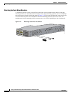
–
Rack-mount the switches. If you have the optional 1150-W power-supply module, first
rack-mount the switch before installing the power-supply module.
–
Connect the RPS cable to the first switch above the RPS 2300. Connect the stack cables to the
first switch above the RPS.
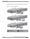
–
Connect the RPS cable to the next switch above the RPS 2300. Connect the stack cables to the
next switch above the RPS.
–
Repeat until all devices are connected.